Hey guys!
Having a bit of trouble settling on a final interleaving method , especially for the primary. Its a 4:5 primary to secondary interleave.
The primary is broken into 4 wound in series , but I'm having a bit of confusion as to how to get the best DCR balance for the B+ as well as longitudinal balance.
I separate the primaries into 4 : P1,P2,P3,P4 . Given P1 is wound first and so on , the length of wire per turn for each is P4>P3>P2>P1 . In my mind it makes intuitive sense that to get the best balance , connecting one end of P1 to P4 would give the best balance as shown in the 2 possible configurations above. Would you guys agree? then again , how do I do this connection ; each winding has 2 possible connection points.
Using the numbers above for each connection . is it best to go 1-2-7-8-3-4-5-6 ?
Its a Push Pull OT running off 4 EL84's. Building for -1db at 20Hz for lower frequency bound. The secondaries are 4,8,16 Ohm taps . Expected output of around 30W.
Thank you so much !
Last edited:
All depends on what is most important in the circuit/application. HF performance, leakage inductance, resistance match, etc. You say nothing about a secondary or its configuration. Resistance match would not be the main design parameter for most uses.
Apologies... I will add more details in the post.All depends on what is most important in the circuit/application. HF performance, leakage inductance, resistance match, etc. You say nothing about a secondary or its configuration. Resistance match would not be the main design parameter for most uses.
I would say high bandwidth is the biggest goal. I'm hoping for at least 20KHz. I also want it to be balanced around the B+ voltage for the push pull application.All depends on what is most important in the circuit/application. HF performance, leakage inductance, resistance match, etc. You say nothing about a secondary or its configuration. Resistance match would not be the main design parameter for most uses.
Best DCR balance comes from bifilar winding both legs of the primary together. Mcintosh used such schemes.
FWIW an appropriate device should already be available. Reinventing the wheel is time consuming at best.
FWIW an appropriate device should already be available. Reinventing the wheel is time consuming at best.

Balance of Rdc plays little role in equality of halves, however balance between capacitances and leakage inductance is more detrimental.
Your best bet for balance is split coil or double bobbin C core.
It is important to guarantee equal P\S capacitances. Also, for class AB duty, it is mostly preferable to apply cross coupling of the primary layers.
Check my posts on series connection of secondary windings (dangerous area).
The good news are, PP transformers are easier than SE ones in terms of interleaving and capacitance distribution, because of voltage gradient symmetry. But not foolproof, make sure you double check all capacitance coefficients.
At end of class A, the hi-freq roll off point goes down, because only will driven the half primary. If the primary halves are coupled as tight as possible, the roll off freq variability decreases within one period at large signal circumstances and the power bandwith will better. This bandwidth variability can detect simply as higher harmonic and intermodulation distortion, but the ear is more rigorous at complex musical program, because this phenomenon causes variable time constant-related distortions too.Also, for class AB duty, it is mostly preferable to apply cross coupling of the primary layers.
DCR balance, or not . . .
For pentodes and beam power tubes, their plate impedance, rp, is relatively high.
Since rp is in series with the primary halve's DCRs, the balance of DCR is not as important as some think.
For triodes, triode wired pentodes, and triode wired beam power tubes, the plate impedance is relatively low.
You might consider this to be a problem.
The solution:
The fix to unbalanced half winding DCRs, is to add a series resistor to the winding that has the lower DCR.
Example, the two DCRs are 95 and 105 Ohms. Just add a 10 Ohm resistor to the 95 Ohm half winding, that equals 105 Ohms, the same as the other half winding.
(I have done that, added a series resistors between the plate winding, and the output tube plate.
Have Fun Winding!
I do not wind my only output transformers.
I simply find it easier to use commercial output transformers, then I sometimes add a fix, if I can.
$0.03
Do you intend to use global feedback around the transformer? If so, leakage inductance from pri to sec will be important. To reduce that, you will want to interleave pri and sec winding layers.
How did you arrive at 4 pri windings?? Windings need to be considered on a single layer by single layer basis.
How did you arrive at 4 pri windings?? Windings need to be considered on a single layer by single layer basis.
Potentiallyincorrect,
Leakage inductance causes a lag of the phase at the secondary, versus the phase at the primary.
That is why you listed its importance; It affects global negative feedback, and the amount of lead compensation that is needed to correct for that lag.
It should Also be remembered that leakage inductance is important, even if global negative feedback is not employed.
Leakage inductance causes high frequency roll off.
$0.03
Here's a suggested primary winding connection - I've just finished 4 OT's for a local amp maker and this is the primary winding connection that was used, dot indicates the winding start - it is quite a common primary connection scheme, 1st and 3rd primary windings form one half of the push pull - 2nd and 4th form the other half of the push pull, they are then connected in series.

Bifilar winding sounds good! Is it not necessary to employ it for both primary and secondary?Best DCR balance comes from bifilar winding both legs of the primary together. Mcintosh used such schemes.
FWIW an appropriate device should already be available. Reinventing the wheel is time consuming at best.
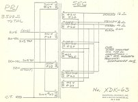
Below is a diagram of a sixty watt PP OPT that I had built around fifty years ago in the heart of the tube audio era. A friend of mine's father was able to get an "experimental pair" built through his company no charge. The mid West (Illinois) was the transformer manufacturing center back then. It's necessary to connect the sections such that they equally cancel the DC core magnetization. I still have these trannies, although not in use right now.
Attachments
I wouldn't think so, the secondary isn't balanced. PP is essentially balanced (differential) to single ended.Bifilar winding sounds good! Is it not necessary to employ it for both primary and secondary?
HollowState gave you a good winding scheme. Maybe he could explore a bifilar variation.
The bifilar winding is very good for tight inductive coupling, but it has huge capacitance. The bifilar winnding isn't well suitable as PP center tapped primary (high self capacitance and limited breakdown voltage) at common tube voltages (300-400V), but it's very good at low impedance, low voltage.
Bifilar windings only work very well in McIntosh's/Gow's Unity Coupling designs, when adjacent turns show the same AC levels, but aren't good in usual PP OPT's, due to the enormous intra winding capacitance. I know the Hafler/Kereos suggestion of doing it although, but it needs crossing the wires one times per turn, and capacitance still remains comparatively high.
Best regards!
Best regards!
Here's a suggested primary winding connection - I've just finished 4 OT's for a local amp maker and this is the primary winding connection that was used, dot indicates the winding start - it is quite a common primary connection scheme, 1st and 3rd primary windings form one half of the push pull - 2nd and 4th form the other half of the push pull, they are then connected in series.
View attachment 1353726
This is a good example of cross-coupling the primaries. The voltage gradient is also equal between P/S layers. If used with inner secondary layers, I would definitely reverse wind the A1 and A2 primary chunks to decrease P/S capacitance.
This is a good example of cross-coupling the primaries. The voltage gradient is also equal between P/S layers. If used with inner secondary layers, I would definitely reverse wind the A1 and A2 primary chunks to decrease P/S capacitance.
To reverse-wind the A1 and A2 primary chunks, would it look like this?
- Home
- Amplifiers
- Tubes / Valves
- Output Transformer Interleaving