Looked like some presentation material, where the presenter would go more in to details? But I found an interesting points about OLGB: "When you’re strapped for loop gain at 20kHz, limit low frequency loop gain to the same value."
I think this is the same thing as kokoriantz was saying before in the thread.
Could somebody hint on a good way of doing this in this amp? I'm afraid wild guessing could create new problems with impedance between stages or similar?
I think this is the same thing as kokoriantz was saying before in the thread.
Could somebody hint on a good way of doing this in this amp? I'm afraid wild guessing could create new problems with impedance between stages or similar?
Looked like some presentation material, where the presenter would go more in to details?
In his life...
🙂
But I found an interesting points about OLGB: "When you’re strapped for loop gain at 20kHz, limit low frequency loop gain to the same value."
I think this is the same thing as kokoriantz was saying before in the thread.
Could somebody hint on a good way of doing this in this amp? I'm afraid wild guessing could create new problems with impedance between stages or similar?
Yes, this point named as "dominant pole freq" and usually formed at the output of VAS stage by placing small ~100-150 pF capacitor around base and collector of the transistor.
This type of correction are not good today.
Check this tread:
????????? ????????? + ???????
Sorry it's in russian, but schematics from the links must be easy to use.
It was a bit hard to follow the thread using using the 'giggle translator', but after failing to follow the conversation I took a look in Self's writings, and the 2-pole compensation he showed seemed like a fairly easy thing to try too, except I need to order some new caps for that.. He seems to have nothing negative to say about it either.
Playing around with some values looking at the phase, it seems to dip to 150-160deg at the beginning of the slope, but I guess that's how it is, and should be? Looking at that OLG peak and twist in the phase makes me feel a bit awkward to it, but it would probably be worth trying.
Playing around with some values looking at the phase, it seems to dip to 150-160deg at the beginning of the slope, but I guess that's how it is, and should be? Looking at that OLG peak and twist in the phase makes me feel a bit awkward to it, but it would probably be worth trying.
Attachments
I took a look in Self's writings, and the 2-pole compensation he showed seemed like a fairly easy thing to try too, except I need to order some new caps for that.
Yes, but feel free to try it as 3-pole like attached.
Out of +-10 dB around 0dB gain freq point phase can be even out of classical "stable" 180 degrees.
Check post #35 in the thread from my previous post.
Keep in mind simple rule. OPS have limited bandwidth, always the less - the better and easier. Any feedback depth at, say, 20 kHz need to fall to -10 dB point at some freq.
Let's pick 60 dB feedback depth and calculate.
1-pole = -20 dB/decade. So -10 dB point will be somewhere at ~60 MHz.
2-pole = -40 dB/decade, -10 point somewhere at 3-5 MHz
3-pole = -60 dB/decade, -10 point somewhere at ones of MHz.
Yes, it is not so straight, but the principle.


Last edited:
Yes, but feel free to try it as 3-pole like attached.
Oh, even more poles! I think I need some time to let that one sink in.. 🙂
Rallyfinnen said:I tried double output pairs now, and then it is no longer stable with a 470p cap across the output (stable with LR though).
I had a similar problem when I 'modified' a Wharfedale S1500 amplifier. The so called modification, was a removal of all SMD circuitry and the creation of an input stage, VAS and output protection circuit. These changes first resulted into a never ending head scratching, because I could not find a way to get a stable amplifier under LTSpice. The solution was to be very careful about input stage's transistor choice and VAS' transistor choice. Both these stages require transistors with a low Ic max which ensure their silicon die is of a small and appropriate area. A large silicon area has more parasitic capacitances which increase the phase change of a propagating signal. Too much phase change changes the status of an inverting input into a non-inverting one, causing severe intense oscillations, which an audio output stage cannot handle.
This forum has thaught me that even if nothing is changed except for one transistor, an otherwise well behaving amplifier, can become unstable and oscillate vigorously.
Your mistake is, you are taking the addition of extra output pairs as a trivial exercise: it is NOT. That kind of change changes the output characteristics, as you are witnessing in your case.
The L12-2 amp I'm playing around with actually had double CFP outputs from the beginning, and I changed it to double EF. I used the MX50SE simulation I found on the forum since it is essentially the same amp, but it had only one output pair.
However, I agree with you that my simulation is far from reality, it does not have the correct transistor models. However, I think simulation helps me to understand what I could try to tweak, and what effect it will have.
I like real life experiments more than simulation, so I hope to do some tweaking and testing on this, but it does seem to get complicated to do that with multiple poles in the compensation. In this case I'm expecting smoke before success 🙂
As it is, it actually seems ok with stability, but required high Iq to get rid of high order harmonics, so I want to tweak it some more and see what happens, and hopefully learn something on the way.
From what I read so far, most people don't expect an amp to be stable with a capacitive load if it has no LR on the output. I've learned a new expression today 'conditionally stable'.
@BesPav
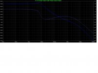
If I understand the 3-pole graph correctly, it seems there is 180deg phase shift and abt 40dB gain around 30kHz? Is this not a problem?
If I understand the 3-pole graph correctly, it seems there is 180deg phase shift and abt 40dB gain around 30kHz? Is this not a problem?
@BesPav
If I understand the 3-pole graph correctly, it seems there is 180deg phase shift and abt 40dB gain around 30kHz? Is this not a problem?
No.
Until gain fall to +10 dB phase doesn't mean at all.
The only region of interest in terms of stability is a +10 : -10 dB.
Here phase must be somewhere inbetween 120 to 170 degrees.
You can read more by searching for "phase margin" and "gain margin".
Last edited:
Right. This is best understood using the Blake and Collins abacus.
And the phase margin we are talking about is the the loop gain.
This is not that easy to measure because it is not as simple as opening the loop. At the point the loop is opened one must maintain in and out impedances at the operating point.
This is easy to simulate using a Tian probe, a better and easier alternative to the Mittlebrook method.
No.
Until gain fall to +10 dB phase doesn't mean at all.
The only region of interest in terms of stability is a +10 : -10 dB.
Here phase must be somewhere inbetween 120 to 170 degrees.
You can read more by searching for "phase margin" and "gain margin".
Thank you for clarifying! I have read some basics on phase and gain margin, but only the phase at 0 gain and gain at 180 phase. I thought the phase margin was valid all the way from low frequency up to 0 gain, and then gain should be below -12dB (?) when phase finally reached 180deg. I guess it was only covering single pole compensation.
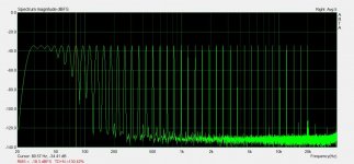
I did some playing around today with different miller cap values, and I could not really see any difference running multitone and FFT in ARTA. Actually in some cases there seemed to be more 'grass' in the +20kHz area with a smaller compensation cap, even if the amp seemed stable. Boosting Iq generally makes much more difference IMHO.
I also did some really quick and dirty test with TMC, and did not see much difference either, except some small improvements with what I would call 'under-bias' where high orders of distortion was still visible above -110dB. The high orders were slightly lower with the TMC. However, this was a really unscientific test.
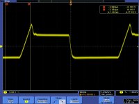
I did a quick test test increasing the current in the VAS by parallelling the 150ohm in the CCS with a 300ohm, and it did nothing to the positive peak, but it did improve the rise time from 24V/us to 38V/us.
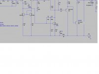
Doing some simulations, I have reduced the OLG to 57dB by using 500ohm emitter resistors in the IPS, decreased feedback resistor to 5k, increased current in the VAS to 6,3mA (nicer rise time) and TMC compensation. In this way I get OLG almost constant to 20kHz, and it simulates as stable.
Are there some more things I should think about/check before going ahead with this?
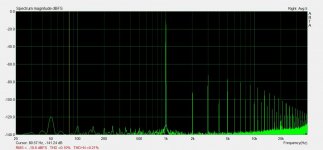
The peak I above I have no clue where it's from. Should I care?
Are there some more things I should think about/check before going ahead with this?
The peak I above I have no clue where it's from. Should I care?
I went ahead and did the mods above, and it seems promising. There are some minor oscillations and wrinkles on the flanks with low Iq though. There is no peak any more, I'm starting to suspect only one channel has this, and the one I modified and tested today might not have had it from the beginning. Will see when I test the other channel after it's modified.
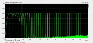
When it comes to distortion it seems to bee similar to before. A little bit more 'grass' visible in the top octave with multitone, but if could actually bee that the (THD+N) floor is lower in the lower part of the spectrum.
When it comes to distortion it seems to bee similar to before. A little bit more 'grass' visible in the top octave with multitone, but if could actually bee that the (THD+N) floor is lower in the lower part of the spectrum.
Finally I have something to try and listen to.
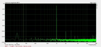
Both channels behave the same, and the square wave response looks nice too.
Iq needs to be around 0,35A (per channel) for best FFT, then it's only 2nd and 3rd harmonics visible around -90dB, some higher harmonics become visible at high output levels around -100db.
Also looking at the square wave flanks before, I came to the same Iq setting.
I set it at about 0,4A because the bias is overcompensated with temp. I guess higher values on the emitter resistors would stabilize this, but I want to run high Iq to have some class A power for normal listening too.
EDIT: emitter resistors are 0.1 Ohm in the model, but they should be 0.15.
Attachments

Last edited:
After some initial listening I'm already convinced, I definitely like it better now. Now I want to put these boards in a chassis and actually use them for something🙂
The Iq unstability is a bit disturbing though, but I guess I can live with it. The initial Iq at startup goes to abt 1A when it's cold, and then settles around 0,4 after warming up. On the bright side it quickly brings the amp up to working temperature 🙂
The Iq unstability is a bit disturbing though, but I guess I can live with it. The initial Iq at startup goes to abt 1A when it's cold, and then settles around 0,4 after warming up. On the bright side it quickly brings the amp up to working temperature 🙂
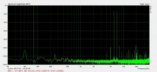
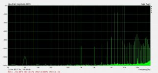
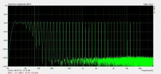
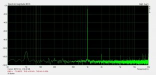
I have done some listening and measurements. Sounds good at low levels, but as measurements show, it gets a little bit rough on higher levels. I tried a cap over R22 too, but could not measure any difference. I think this is the end of this project, but the concept of high bias class AB intrigues me, so after some looking around, I ordered the hifisonix kx PCB's (and one blameless) from Jim's audio. The sx would have sufficed for my needs, but I read something about problems sourcing components for it. The ks is a bit similar to this (double EF pairs, high bias, TMC compesation..), but properly executed 🙂
Attachments
-
 imd 3V 4ohm.jpg88.6 KB · Views: 60
 -
 multitone 3V 8ohm.jpg112.8 KB · Views: 59
 -
 imd 3V 8ohm.jpg88.3 KB · Views: 57
 -
 10V 8ohm.jpg81.8 KB · Views: 58
 -
 imd 10V 8ohm.jpg85 KB · Views: 58
 -
 multitone 10V 8ohm.jpg113 KB · Views: 52
 -
 multitone 10V 4ohm.jpg112.8 KB · Views: 52
 -
 imd 10V 4ohm.jpg84.7 KB · Views: 101
 -
 10V 4ohm.jpg82.9 KB · Views: 111
Last edited:
- Home
- Amplifiers
- Solid State
- Output stage CFP to EF on LJM amp?