@Ralleyfinnen,
If your DAC has too much gain attenuate it with a resistor divider network.
If you decrease the closed circuit loop gain this pushes the feedback gain to out to a higher frequency where this declines to 0dB - depending on proportions getting further away from that designed into the compensation scheme. You don't have to go there.
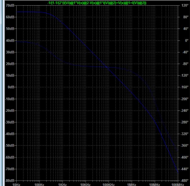
your actual OLBW is simulated at post 6 is
required OLBW is
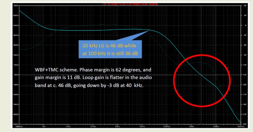
See design example of high quality amp
Ovation e-Amp: A 180 Watt Class AB VFA Featuring Ultra Low Distortion
required OLBW is
See design example of high quality amp
Ovation e-Amp: A 180 Watt Class AB VFA Featuring Ultra Low Distortion
Attachments
Thank you for all the replies!
I have taken one first step on this slippery road, and will probably end up in the ditch 🙂
I modified the schematic to better mimic the L12-2 with double outputs better, and some resistor values for current sources etc.
I changed the existing compensation cap values to 0, and then tried a cap over the feedback resistor (which I also changed for lower gain). Suitable cap value seems to be around 5p. This gives better OLBW , and as far as I can understand it stays within the recommended margins? -So in theory it seems to do the trick.
How about in practice?
I have seen some advice against this, so what do you say about it, if RC and LC is used on the output?
The transistor models in the simulation are not correct, so I need to find replacements to simulate this correctly, or just try it on the boards..
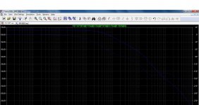
Sorry about the bad screenshots..
I have taken one first step on this slippery road, and will probably end up in the ditch 🙂
I modified the schematic to better mimic the L12-2 with double outputs better, and some resistor values for current sources etc.
I changed the existing compensation cap values to 0, and then tried a cap over the feedback resistor (which I also changed for lower gain). Suitable cap value seems to be around 5p. This gives better OLBW , and as far as I can understand it stays within the recommended margins? -So in theory it seems to do the trick.
How about in practice?
I have seen some advice against this, so what do you say about it, if RC and LC is used on the output?
The transistor models in the simulation are not correct, so I need to find replacements to simulate this correctly, or just try it on the boards..
Sorry about the bad screenshots..
Attachments
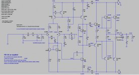
The root of your problem could lie in the LTP driving the Vas into saturation. The values of R7 (100R) and R12 (150R) suggest the standing current in the LTP CCS is higher than in the Vas CCS. The values look to have been transposed but if not they would have to have been plucked out of the air.
Would this be a problem only at high output/clipping?
I adjusted those values a bit according to a schematic I found for the L12-2
I adjusted those values a bit according to a schematic I found for the L12-2
Have you considered making R18 zero? You will have to reduce R10 & R11 a lot, say <20 ohms. Keep the Miller cap 100pF.
Not really.. since I don't know what I would gain from it..
I have not had time for this now, but will write more after trying something, and probably blowing them up 🙂
I have not had time for this now, but will write more after trying something, and probably blowing them up 🙂
Ok! I'm like a clueless blonde! 🙂
Just as a general preference, I like to have some R in electrical circuits to damp ringing etc, would this apply in amps too? I imagine low resistance in combination with stray capacitance and inductance could promote ringing? Maybe also pickup of magnetic fields on the PCB etc?
Maybe lowering the resistance would be ok too? To me it seems like the original 68ohms is pretty low relative to the current in the circuit? But then again, there are many things I don't understand! 🙂
Actually, I ordered some small caps today to try real life experiments and compare to what the simulations suggest.
I have a preliminary plan in my head:
1 Remove C6(?) on the input stage, and decrease the miller cap to around 30p, change feedback resistor to 5k (which seems ok in simulation).
2 Do some basic stability tests to verify and adjust the cap.
3 Measure
4 Listen
If I don't like it:
Try removing the miller cap too, and just put a capacitor over the feedback resistor, and then 2-4 again.
I probably have smoke before I get so far 🙂
I'm just thinking that the first adjustment could be 'good enough', it sounded ok as is with high Iq, so maybe some small tuning could be enough. Simulation suggests it's compensated 'very safe' as is, maybe it's because I changed the output topology, I don't know how that affects the loop.
Last edited:
Trust your instincts. Simulators don't simulate everything: garbage in, garbage out. 😎Just as a general preference, I like to have some R in electrical circuits to damp ringing etc, would this apply in amps too? I imagine low resistance in combination with stray capacitance and inductance could promote ringing? Maybe also pickup of magnetic fields on the PCB etc?
There is a thread on the LJM M50SE see MX50SE LJM 2015 the origins which are derived from one of Self's circuits.
You can see from this that your values for R7 and R12 at 100R and 150R respectively are transposed. Somewhere later in the thread a contributor increased R12 to 220R.
The effect of increasing R12 is to reduce the Vas transistor current and the gm of the stage which is roughly 40m Siemens per m.a. A race car does not run better if someone puts 91 Octane in the tank by mistake.
Another thing to keep in mind is that the CFP stages have better thermal stability than EF2 stages as these have two forward biased emitter junctions which will conduct more with temperature increase and care is needed with the Vbe multiplier.
When testing an amplifier module it is best to include some means of current limitation to guard against failure at turn on. The method I use is to fit 5W 100R wire wound resistors in the supply lines. This circuit does without electronic load line limiting and would need rail fuses. You could wire these resistors across the holders without the fuses in place. You can deduce the standing current by measuring the voltage drop across these points.
If there is a fault these resistors will heat up rapidly. Heat can be sensed with a moistened finger. I keep use one hand to do that with my other hand on the power switch.
I am at a holiday property and am packing up to return home today so I am keeping this reply short for that reason.
I have a adjustable dual 24V current limited bench supply (max 1,5A) and a good scope at work, so I try to use them for powering up and doing experiments (when I have some dead time at work).
After initial tests I can take it home and do distortion measurements and listening using a 30V linear supply.
After initial tests I can take it home and do distortion measurements and listening using a 30V linear supply.
I actually did a 'quick and dirty' now: replaced the feedback resistor with 5k, and tried some small caps I had from before. 6,8p across the feedback resistor and no miller cap is a no go. Also 6,8p as miller cap is a no go. Using two of the standard 100p in series (50p) as miller cap seems stable. I need to wait for the caps I ordered to find the 'limit'.
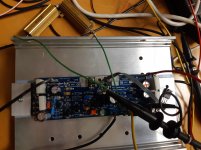
I can see that the bias seems 'overcompensated' as it is now, at least with a high Iq setting. At startup Iq goes to abt 1A, and then settles at 0,45A (set value) when it heats up. This is in abt 1min with the sensing transistor mounted on top of the outputs as in the picture.
Attachments
Stability Test flying by the seat of the pants method
If your amplifier is stable it should be possible to adjust the standing current down to a handful of m.a.
It might be time to turn to some science.
If your amplifier is stable it should be possible to adjust the standing current down to a handful of m.a.
It might be time to turn to some science.
🙂
I will have to wait and see until I get the caps and have time to do some measurements.
It can for sure be adjusted down as it is, and I did so only looking at the scope, but I have not done it looking at FFT. Scope looked good at low currents (amp-needle did not move on the bench supply).
I would say that on most amps I played with, I see FFT improvements at a few watts (my normal listening level) running high Iq, and also prefer the sound with this setting. I think there is some science behind that too.
I forget to thank people for helping, but seeing all the replies here reminds me: Thank you!
I did not expect so much support, since this is kind of a waste of time that will probably end up in smoke, but also a learning project for me.
I'm trying to understand amps better, and also correlate between measurement and listening impressions. A good example of my confusion is this L12-2 amp, which measured really good, but I did not like the sound. On the other hand I like the sound of the JLH69 amps, and by tweaking them I improved both measured and subjective performance (thanks to kokoriantz for the sublimed JLH). However, I find it a bit strange that such small differences can be heard. If it was on the -30dB level I would not doubt it, but -80 or -90dB distortion.. confusing stuff.
What level of Iq are you thinking of here. The plot of current against Vbe of a Darlington pair is steep outside the turn-on region. Think about the power level where your crossover will be operating and where the impacts will be less prominent.
I'm trying to understand amps better
Mostly all bicycles was already invented before us...
https://www.diyclassd.com/img/upload/doc/an_wp/WP_AES123BP_the_engineers_survival_guide.pdf
- Home
- Amplifiers
- Solid State
- Output stage CFP to EF on LJM amp?