Hi Ravi ,
Could you please introduce yourself..by sending an email to me....
regards,
K a n w a r
Could you please introduce yourself..by sending an email to me....
regards,
K a n w a r
powerbecker said:snip
U R website look nice
Hi
Really?
"....Website is under construction....."
... but don't hold your breath, its been under construction for the last 2 years or so....
Jan Didden
janneman said:
... but don't hold your breath, its been under construction for the last 2 years or so....
Jan Didden
Hi Life of Heart,
The Slew rate of my website's development is very Low......
It Might took several another LightYears to make it complete......Unless Jan would help me to finalize it........
😀 😀 😀 😀 😀 😀 😉 😉
K a n w a r
snip
The Slew rate of my website's development is very Low......
Hi Kanwar
a good thing need some time!
The only interesting what I find there is :
"WORLD’s FIRST PROFESSIONAL IGBT AMPLIFIER"
Please, can You explain to me which world You mean?😉
Regards
Heinz!
The Slew rate of my website's development is very Low......
Hi Kanwar
a good thing need some time!
The only interesting what I find there is :
"WORLD’s FIRST PROFESSIONAL IGBT AMPLIFIER"
Please, can You explain to me which world You mean?😉
Regards
Heinz!
snip
Meanwhile, I have devised another circuit for short circuit protection.....and reactive discharge control
It senses both output Current as well as output voltage as key parameters , then the logic is applied to carry out the requisite decision...
If output voltage is Zero and current through Mosfet is High[enough high to prevent false triggring due to reactive loads], then the input signal to the amp is muted[input is shorted to ground]
If output voltage is high and current through mosfet is also high or above threshold of reference then no muting...amp is safe
If output voltage is low [tends to zero] and current is above reference threshold of permissible value [in accordance with SOA curve] then input signal is attenuated until it appears to be safe.....
correct me if i were wrong in any aspect....
regards,
K a n w a r
Hi Kanwar,
I believe even though Your circuit is better than a fuse or nothing
it will work not really shure.
Imagine the following situation:
The load is a big choke and the outputvoltage is maximal.
So Vds is small, and the outputcurrent starts up from zero until he reached the current-triggerpoint for high outputvoltage.
Now the input will shut down and so the outputvoltage is zero.
From that moment the outputcurrent don`t grow further but has still about the same value as before.
What mean this for the active outputfets?
They carry the max. current and at the same time they get half of their operational voltage.
That will be too much powerwastage for them!
So it`s better to observe always the fetcurrent- and voltage and to limit if necessary (in accordance with their soar- or powerlimits) their steering.
Regards
Heinz!
powerbecker said:The only interesting what I find there is :
"WORLD’s FIRST PROFESSIONAL IGBT AMPLIFIER"
Please, can You explain to me which world You mean?😉
Regards
Heinz!
Hi HeinZ,
The same world in which you & I live.....
We designed the World,s First IGBT Professional amp for professional - audio user segment....whereas there are lot of IGBT amps present in HI-FI Home user segment, I dont think there is any amp which uses igbt's at output in a pro-segment other than ours, If any exist please tell me .... so that i can correct my statement....
powerbecker said:snip
Hi Kanwar,
I believe even though Your circuit is better than a fuse or nothing
it will work not really shure.
Imagine the following situation:
The load is a big choke and the outputvoltage is maximal.
So Vds is small, and the outputcurrent starts up from zero until he reached the current-triggerpoint for high outputvoltage.
Now the input will shut down and so the outputvoltage is zero.
From that moment the outputcurrent don`t grow further but has still about the same value as before.
What mean this for the active outputfets?
They carry the max. current and at the same time they get half of their operational voltage.
That will be too much powerwastage for them!
So it`s better to observe always the fetcurrent- and voltage and to limit if necessary (in accordance with their soar- or powerlimits) their steering.
Regards
Heinz!
Yes, you are right....The VDS must also be taken into consideration as well along with Vout and Ids..Thanks for the suggestion....Now it would be more accurate protection scheme...
regards,
K a n w a r
Hi HeinZ,
The same world in which you & I live.....
We designed the World,s First IGBT Professional amp for professional - audio user segment....whereas there are lot of IGBT amps present in HI-FI Home user segment, I dont think there is any amp which uses igbt's at output in a pro-segment other than ours, If any exist please tell me .... so that i can correct my statement....
Hi Kanwar
That I missed:- audio user segment....
Regards
Heinz!
powerbecker said:
Hi Kanwar
That I missed:- audio user segment....
Regards
Heinz!
Thanks......once again ..
K a n w a r
Hi Janneman,
I am just waiting for your excellent comments.......
Hi AndrewT ,
Have you came up with some specific conclusion regarding N-Vmosfets, if yes...please let me know.....
best regards,
K a n w a r
I am just waiting for your excellent comments.......
Hi AndrewT ,
Have you came up with some specific conclusion regarding N-Vmosfets, if yes...please let me know.....
best regards,
K a n w a r
Hi Workhorse,
No real conclusions yet, I have not completely written them out of my design arsenal.
You have been very thorough to find such an exceptional FET that does support your contention that this FET can stand a short term pulse better than BJT. Almost all the other FETs I have looked at are no better and usually worse than BJT in this respect.
You win that point.
I now wonder if this FET or similar would be ideal for rail disconnecting in event of output stage failure? To protect the speaker! Or even as an alternative to a triac to short out both supply rails and blow the fuses.
Hi to all!
This thread shall never ending.😉
So back to the beginning : the search for a speaker-protection, when the amp fails and try to kill the speaker with high DC-output.
The question seems not to be the actual DC-detector but
which is the best way to take away the DC -voltage from output.
I always prefers a kind of crowbar.
I have for this 2 propositions.
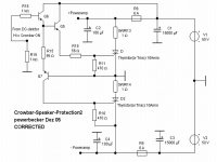
The first use 2 thyristors (or triacs) which shutdown both supplyrails after the supply-fuses to ground at the same time.
Thyristors are cheap and robust and can carry high peakcurrents.
Neverless this it will be good practice to limit the current with a small resistor in serie which should be also very robust.
One example for this kind I show in the attachment.
There is also a simpel circuit, but the steering-part is not tested!
Regards
Heinz!
This thread shall never ending.😉
So back to the beginning : the search for a speaker-protection, when the amp fails and try to kill the speaker with high DC-output.
The question seems not to be the actual DC-detector but
which is the best way to take away the DC -voltage from output.
I always prefers a kind of crowbar.
I have for this 2 propositions.
The first use 2 thyristors (or triacs) which shutdown both supplyrails after the supply-fuses to ground at the same time.
Thyristors are cheap and robust and can carry high peakcurrents.
Neverless this it will be good practice to limit the current with a small resistor in serie which should be also very robust.
One example for this kind I show in the attachment.
There is also a simpel circuit, but the steering-part is not tested!
Regards
Heinz!
Attachments
Hi
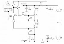
The second crowbar works with a strong relais which shut down the output without current in his coil.
The shutdown is not direct to ground because there are some diodes in serie. So a shortcut for the amp-offsetvoltage is avoided. As the thyristor-circuit 😉 it also latches.
The 4 diodes one can get simply from a big (25A) bridge-rectifier.
In the attachment the circuit, also not tested!
Regards
Heinz!
Attachments

Hi Power,
protection2 shows a pair of crowbars. What Triac do you recommend?
Protection 1. How does it operate? What does the bridge rectifier do?
protection2 shows a pair of crowbars. What Triac do you recommend?
Protection 1. How does it operate? What does the bridge rectifier do?
The bridge is drawn wrong.
Correctly hooked up it will give two diode drops in either direction.
Correctly hooked up it will give two diode drops in either direction.
AndrewT said:Hi Power,
protection2 shows a pair of crowbars. What Triac do you recommend?
Protection 1. How does it operate? What does the bridge rectifier do?
Hi Andrew
1. the biggest You can get cheap!😀
TIC 263D : 400V 25A 2,10€
TYN416 : 400V 16A 0,90€
2.
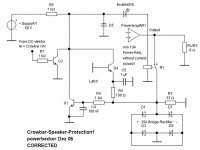
all is Ok :The relay gets current from R6 , contact is open.
The amp fails : the detector-circuit put a H to R7 and Q3 takes the current from relais : output is now switched to D1/3.
So outputvoltage is max +/- 2V and a big current flow through
the bridge.
Voltage on R2 (+/-2V) switch, dependend of polarity either
Q1 or Q2 on.
So for the case that Q3 is already off the relaiscoil don`t get current and held the outputvoltage down till You switch off the whole amp or the DC disappears.
A benefit can also be that the normal working amp never "sees"
a direkt short-cut, also the relais gets from one reason no current.
Regards
Heinz!
djk said:The bridge is drawn wrong.
Correctly hooked up it will give two diode drops in either direction.
Thank You I see it!
Hi Heinz,
Using the right polarity for the transistors make the circuits easier to understand 😉
In your thyristor circuit, I think Q4 should be PNP and collector/emitter reversed. Furthermore R15 and R18 seems to me to have a too low value for up to 50V gate drive. Well, it depends on how high is high for the DC detector.
In the relay circuit, I think Q2 should be NPN if you want to switch it on by a negative voltage (-2V) on its emitter. Maybe use a bipolar cap for C1; you never know what the polarity will be. Or put it somewhere else in the circuit.
Steven
Hi Steven,
thank You! Sorry I was tired.
snip
Using the right polarity for the transistors make the circuits easier to understand 😉
How true!
snip
In your thyristor circuit, I think Q4 should be PNP and collector/emitter reversed. Furthermore R15 and R18 seems to me to have a too low value for up to 50V gate drive. Well, it depends on how high is high for the DC detector.....
and also from the necessary current for shure switching the thyristor/triacs.
I have done a correction
Regards
Heinz
Attachments
snip
Steven:
In the relay circuit, I think Q2 should be NPN if you want to switch it on by a negative voltage (-2V) on its emitter. Maybe use a bipolar cap for C1; you never know what the polarity will be. Or put it somewhere else in the circuit.
Steven, also right!
Thank You
Heinz!
Steven:
In the relay circuit, I think Q2 should be NPN if you want to switch it on by a negative voltage (-2V) on its emitter. Maybe use a bipolar cap for C1; you never know what the polarity will be. Or put it somewhere else in the circuit.
Steven, also right!
Thank You
Heinz!
Attachments
- Status
- Not open for further replies.
- Home
- Amplifiers
- Solid State
- Output protection