Why this irony, Mike ? By my opinion this circuit must be trying to solve in all context of amp and isn't so easy ( if we can designed it seriously, not like toy for children ).


Actually, we're not all that interested in how fast the MOSFETs turn on. We want them to turn OFF quickly. We can forgive milliseconds coming on as long as the implied power dissipation is not large - and it should not be huge, as it will be seldom that an amp is turned on into a full power signal situation.Unfortunately PVI gate drives make MOSFET switching virtually as slow as an EM relay....insufficient current to charge the MOSFETs input capacitance fast enough....See pg 8 here:
(For the nay-sayers; yes, it does happen, and yes, we need to design it so the lead singer's girl friend can't kill our amps, but it does happen infrequenctly, that's all I meant.)
IRF notes in their app notes on the PVI units that they (at least some of them, notably the PVI1050) contain onboard circuitry to speed up the turn off. While this is comforting, you can also add a set of suspenders to your belt and add some fast turn off circuitry of your own if this is deemed to be a problem.
The PVI1050 turns out two isolated 5V outputs. Obviously, we need them in series for maximum enhancement of non-logic level MOSFETs.
For those who can't see what's happening without a schematic: I drew up some of the circuits I've referred to and put them on my web site. See http://www.geofex.com/FX_images/MOSFET-Protection.pdf for conceptual schematics.
Why not exact schematics? I built i mine along the lines of Fig 6. as I had +/-32V rails and a tube of IRF9630 P-channel MOSFETs. This let me just enhance by pulling the gates down to ground. For higher rails you need higher voltage MOSFETs and that runs you quickly into using a high side driver, which I have not built. So I'm not putting up schemos for them. I fully believe that someone who knows a little about power electronics can make the high side drive happen ( I have built high side drives, but not for this application).
The whole trick here is in the detection circuit, and mating that to two N-channel MOSFETs, one in the +V rail and one in the -V rail. The detector needs to detect DC as a proxy for a failed output device, and take some action. The action should be to turn both high and low side MOSFETs off, it should be done as quickly as possible, and it should be latching.
There is no real hope of saving an output device from SOA failure with this scheme - it's not fast enough.
This idea is a means to remove a relay from the audio path. If you like relays and are satisfied with them, fine, you don't need to read further. That's not a question which is germane to this discussion.
As to questions of whether protection is needed at all, I belive I covered that as well - if you don't want protection, or think it's not needed, fine, you don't need to read any further either. That's not a question which is germane to this discussion, either.
My personal opinion is that there are faults I cannot design out ( I did at one time design switching power supplies for a living, and Mother Nature taught me some things about faults) so my opinion is that faults will happen, and we can at least limit the damage. Turning off the DC power is the best way I can think of to limit collateral damage.
OK, Mike, did I get the synopsis correct?
Re: Re: Re: Re: General protection mumblings
I guess relays can only hope to protect their kin, electromechanical devices like speakers, apt to be damaged by energy as power integrated over relatively long (electronically speaking) times.
Absolutely, and that was my point all along.
With respect to SOA, you are right, the ground return current measurement only takes care of maximum instantaneous current and is conservative in SOA protection if we design for the full rail voltage across the involved device. In an actual situation this voltage may be lower.
Another limitation is in principle it cannot relialbly detect a rail to rail (balanced, shoot through) overcurrent.
A more complete and complex alternative then is separate and simultaneous current sensing on both rails.
Rodolfo
mikeks said:
.....
The difficulty here is that a relay cannot hope to open fast enough to give foolproof SOA protection....
I guess relays can only hope to protect their kin, electromechanical devices like speakers, apt to be damaged by energy as power integrated over relatively long (electronically speaking) times.
....There is no excuse for slack design in this regard....
Absolutely, and that was my point all along.
With respect to SOA, you are right, the ground return current measurement only takes care of maximum instantaneous current and is conservative in SOA protection if we design for the full rail voltage across the involved device. In an actual situation this voltage may be lower.
Another limitation is in principle it cannot relialbly detect a rail to rail (balanced, shoot through) overcurrent.
A more complete and complex alternative then is separate and simultaneous current sensing on both rails.
Rodolfo
From a relay .... liker. Flame on !
Anyhow, at some current level a Mosfet may come out of saturation. This will increase it's dissipation drastically. When setting your gate drive you'll have to increase the voltage over what you may calculate as sufficient. Or parallel them to share the load and reduce the maximum current density.
We saw this with some Carver Pro amps when commutators would short unexpectedly. The devices were Mosfets used as switches. Same idea, different application, same problems.
As I understand it, we are attempting to keep a circuit defect from destroying the load (speaker). Which I hold the designer morally responsible to do to the best of their ability and art. No excuses. Some speakers do burn.
-Chris
Re: Re: Re: Re: Re: General protection mumblings
No...a complete solution requires that you sense instantaneous current through and voltage across your output devices....AKA SOA protection...
ingrast said:
A more complete and complex alternative then is separate and simultaneous current sensing on both rails.
Rodolfo
No...a complete solution requires that you sense instantaneous current through and voltage across your output devices....AKA SOA protection...
R.G. said:
Actually, we're not all that interested in how fast the MOSFETs turn on. We want them to turn OFF quickly. We can forgive milliseconds coming on as long as the implied power dissipation is not large - and it should not be huge, as it will be seldom that an amp is turned on into a full power signal situation.
I reckon i'll need the MOSFETs in my supply rail to turn as one....so to speak...and as rapidly as possible....(tens of milliseconds for each rail is far too long!)..
This minimises switching losses, and potentialy prevents asymmetrical turn-on being spuriously detected as a DC fault...
R.G. said:The PVI1050 turns out two isolated 5V outputs. Obviously, we need them in series for maximum enhancement of non-logic level MOSFETs.
I reckon you'll need three in series to minimise Rds(on)..........
R.G. said:For those who can't see what's happening without a schematic: I drew up some of the circuits I've referred to and put them on my web site. See http://www.geofex.com/FX_images/MOSFET-Protection.pdf for conceptual schematics.
I think you'll find your conceptual schematics #7 through to #9 are conceptualy in error..(OK....couldn't resist that! 😀)
...each supply rail switch will require it's own gate drive...which you've not shown...may confuse folk....
Never underestimate the power of clarity.....

Upupa Epops said:Twony pages of discussion and still any concrete schematic. Your productivity isn't miracle, guys 🙂 .
Well, once you know what you WANT, the schematic is a trivial thing.....
Jan Didden
Re: Re: Re: Re: Re: General protection mumblings
Well, I don't want to be seen as promoting mikeks, but I feel that SOA modelling is the only way to keep the amp from failing due to overload AND to get the max power out of a given set of output devices and power supply. Supply current measurement can be usefull to limit the output current, but what Ic at which Vce? Unless you do SOA limiting, you throw away some output capability.
So for me the best system would be SOA limiting, complemented with something like a relay that disconnects the load in the event that something in the amp blows up despite the first system. That relay then has to protect the speaker and not the amp (which is already defect at that point) so as stated that relay can easily take 100mS to do its job, thespeaker will survive that.
Jan Didden
ingrast said:
I guess relays can only hope to protect their kin, electromechanical devices like speakers, apt to be damaged by energy as power integrated over relatively long (electronically speaking) times.
Absolutely, and that was my point all along.
With respect to SOA, you are right, the ground return current measurement only takes care of maximum instantaneous current and is conservative in SOA protection if we design for the full rail voltage across the involved device. In an actual situation this voltage may be lower.
Another limitation is in principle it cannot relialbly detect a rail to rail (balanced, shoot through) overcurrent.
A more complete and complex alternative then is separate and simultaneous current sensing on both rails.
Rodolfo
Well, I don't want to be seen as promoting mikeks, but I feel that SOA modelling is the only way to keep the amp from failing due to overload AND to get the max power out of a given set of output devices and power supply. Supply current measurement can be usefull to limit the output current, but what Ic at which Vce? Unless you do SOA limiting, you throw away some output capability.
So for me the best system would be SOA limiting, complemented with something like a relay that disconnects the load in the event that something in the amp blows up despite the first system. That relay then has to protect the speaker and not the amp (which is already defect at that point) so as stated that relay can easily take 100mS to do its job, thespeaker will survive that.
Jan Didden
Re: Re: Re: Re: Re: Re: General protection mumblings
Definitely, but then it is likely the cost of actual SOA computation is higher (plus degraded reliability) than the differential cost of higher rating output devices. Except for the case of extreme power where the best available devices are pushed to their limits.
Rodolfo
janneman said:
...to get the max power out of a given set of output devices and power supply. ...Unless you do SOA limiting, you throw away some output capability....
Jan Didden
Definitely, but then it is likely the cost of actual SOA computation is higher (plus degraded reliability) than the differential cost of higher rating output devices. Except for the case of extreme power where the best available devices are pushed to their limits.
Rodolfo
Jan: OTT i just wanted to pop in and thank you for translating that very interesting and beautifully compiled article about distorsion figures, published in AudioXpress (this new issue).
Nice to hear from Jean Hiraga again, he is one of the DIY audio constructors i respect the most. In this article he enlights some of the mysteries of distortion, not only seen from a purely mathematical viewpoinbt (like those guys who say just keep the distortion as close to zero at any cost). Hiraga successfully explains some of the artistic angles of amplifier construction. Unfortunately only in tube amplifiers, but i guess these guidelines apply to amplifiers in general.
Keep up the Good work Jan! 🙂
Lars Clausen
Lars Clausen said:Jan: OTT i just wanted to pop in and thank you for translating that very interesting and beautifully compiled article about distorsion figures, published in AudioXpress (this new issue).
Nice to hear from Jean Hiraga again, he is one of the DIY audio constructors i respect the most. In this article he enlights some of the mysteries of distortion, not only seen from a purely mathematical viewpoinbt (like those guys who say just keep the distortion as close to zero at any cost). Hiraga successfully explains some of the artistic angles of amplifier construction. Unfortunately only in tube amplifiers, but i guess these guidelines apply to amplifiers in general.
Keep up the Good work Jan! 🙂
Lars Clausen
Yes it is an interesting article isn't it. It clearly shows that we are still a long way from mapping measurements to perceptions. I must say I do not always agree with Hiraga, but the man has so much experience that you always pick up something worthwhile from his articles or discussions.
I once had the privelige to visit him in Paris and listen to his system, and I have never, never again heard something so lifelike and realistic. He is a modest person who doesn't put himself on the foreground, but he could run circles around a lot of the current wellknown designers!
Jan Didden
Re: Re: Re: Re: Re: Re: Re: General protection mumblings
Rodolfo,
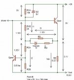
That depends on your view. Attached is my SOA modelling for my output stage, single pair of devices (no, I won't say which 😉 ). As you can see, with multiple breakpoints, I get most of the theoretical capability. The cost in components (both poloarities) is 2 small signal diodes, 2 small signal transitors, 2 zeners and a handful of resistors. I think it is worth it.
Jan Didden
ingrast said:
Definitely, but then it is likely the cost of actual SOA computation is higher (plus degraded reliability) than the differential cost of higher rating output devices. Except for the case of extreme power where the best available devices are pushed to their limits.
Rodolfo
Rodolfo,
That depends on your view. Attached is my SOA modelling for my output stage, single pair of devices (no, I won't say which 😉 ). As you can see, with multiple breakpoints, I get most of the theoretical capability. The cost in components (both poloarities) is 2 small signal diodes, 2 small signal transitors, 2 zeners and a handful of resistors. I think it is worth it.
Jan Didden
Attachments
Re: Re: Re: Re: Re: Re: Re: General protection mumblings
The cost of triple slope SOA protection circuit will always be less than that of a single power transistor...
Using higher rated devices will not protect them from a direct short to ground or opposite-polarity supply rail....
ingrast said:
Definitely, but then it is likely the cost of actual SOA computation is higher (plus degraded reliability) than the differential cost of higher rating output devices. Except for the case of extreme power where the best available devices are pushed to their limits.
Rodolfo
The cost of triple slope SOA protection circuit will always be less than that of a single power transistor...
Using higher rated devices will not protect them from a direct short to ground or opposite-polarity supply rail....
Re: Re: Re: Re: Re: Re: Re: Re: General protection mumblings
...and the schematic...?
janneman said:
Attached is my SOA modelling for my output stage.........Jan Didden
...and the schematic...?
This is how it looks for point B on the urve, I'm sure you recognise it Mike. The odd thing that was not in your article IIRC is the part between zero and 9V Vce. That one took some time to figure out.
But I'm not going to tell more about it, because it is going to be part of an article (hopefully, eventually).
Also, it isn't tested yet. I have constructed the "I/V" display system designed by Peter Baxandall many years ago, and that is working now. I will use that to display the contour of the full I/V protection in all 4 quadrants.
Jan Didden
Attachments
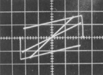
This is a picture made by Baxandall of the QUAD 405 I/V contour including 4- and 8-ohms resistive load lines. Mine are not so nice yet mainly because I can't do long-time exposures on the scope with my simple digital camera; the picture consists of many slow-moving points.
I am awaiting delivery of a used HP variable persistence display, hopefully I can get at least as nice pictures then!
Jan Didden
Edit: hor 20V/div, vert 5A/div
I am awaiting delivery of a used HP variable persistence display, hopefully I can get at least as nice pictures then!
Jan Didden
Edit: hor 20V/div, vert 5A/div
Attachments
Re: Re: Re: Re: Re: Re: Re: Re: General protection mumblings
Well, I do not want to start an argument that in the end can only be settled with actual working designs.
Yet I cannot help note costs (even in DIY frame, how do we rate our time) imply not only direct component costs, but PCB layout, real state, drills, assembly, and testing/debugging. This is to be compared to the *incremental* cost of a higher rating device if it is possible. And not taking into consideration reliability of the added circuitry plus effects on bare ampifier performance that should eventually be demonstrated as negligible under normal operating conditions.
Actual short circuit energy is dependent on power supply capacity, and sense and shutoff protection response time.
This nonwithstanding, the idea has merits and deserves to be explored. Jan, go for it.
MOS power devices for its part have different protection requirements.
Rodolfo
mikeks said:
The cost of triple slope SOA protection circuit will always be less than that of a single power transistor...
Using higher rated devices will not protect them from a direct short to ground or opposite-polarity supply rail....
Well, I do not want to start an argument that in the end can only be settled with actual working designs.
Yet I cannot help note costs (even in DIY frame, how do we rate our time) imply not only direct component costs, but PCB layout, real state, drills, assembly, and testing/debugging. This is to be compared to the *incremental* cost of a higher rating device if it is possible. And not taking into consideration reliability of the added circuitry plus effects on bare ampifier performance that should eventually be demonstrated as negligible under normal operating conditions.
Actual short circuit energy is dependent on power supply capacity, and sense and shutoff protection response time.
This nonwithstanding, the idea has merits and deserves to be explored. Jan, go for it.
MOS power devices for its part have different protection requirements.
Rodolfo
Well, Rodolfo, in a sense you are right, I think I must have spend at least two or three full days to figure out the protection circuit. I don't know what that is worth commercially. Just doubling the output devices would indeed be much easier.
Anyway, I'll let you know how it comes out.
Jan Didden
Anyway, I'll let you know how it comes out.
Jan Didden
I hope this isn't a digression but my experience has been that by far the most common event that triggers VI protection (assuming there is any) is a simple short at then binding posts. If at the amp binding posts it is mostlikely because they are very close together and invite strands of bare wire or the butt-end of spade connectors to contact the opposite post. Trying to make the dconnection in a cramped awkward space just make the probability higher. On the speaker end the biggest fault lies in using posts laking insulation gg gold plate looks so much more "High-End" than red and black plastic.
The point of the above is while VI-limiting circuits are very important, it is good to remind ourselves they are in part a "fall back" for events that shouldn't be allowed to happen in the first place.
My inspiration for this post came from seeing an amp recently that had competent VI-limiting but also had impressive gold plated binding post that just cried out to have a screw driver, hairpin or the cat's brass name tag laid across them!
- Status
- Not open for further replies.
- Home
- Amplifiers
- Solid State
- Output protection