Which is why you want sustained beta drivers in EF2 (or even EF3 predriver). The output tranny doesn’t have much gain at high or low current, so it’s got to be made up SOMEWHERE.
No, I'll probably use around 100 - 200W most of the time. I just want the " power " to be " there " if needed .One questions whether 500 W is actually needed or just wanted
@tomchr @wg_ski For 3db , going from 500W to 250W would be wise, less heat and " stress" on the woofer.
+-45v DC might be enough for 2 ohm ?.
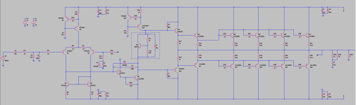
This is what I came up with so far ( some blameless inspired, ( I've built this before with +-35v with 2sc4468 / 2sc1965 with success ).
Some VI Limiter's might be needed here ?. I will surely add a speaker protection ( dc detect ).
output " zobel " inductor might not be needed , thick short wires from the amp to the sub . ( amp will be next to the sub ) .
MPSA92 and MPSA42 ( MPSA43 in LTspice because I don't have MPSA42 for simulation ).
- Any benefit to go darlington for the Vbe multip ?. Faster " temperature compensation " or not ?.
+-45v DC might be enough for 2 ohm ?.
This is what I came up with so far ( some blameless inspired, ( I've built this before with +-35v with 2sc4468 / 2sc1965 with success ).
Some VI Limiter's might be needed here ?. I will surely add a speaker protection ( dc detect ).
output " zobel " inductor might not be needed , thick short wires from the amp to the sub . ( amp will be next to the sub ) .
MPSA92 and MPSA42 ( MPSA43 in LTspice because I don't have MPSA42 for simulation ).
- Any benefit to go darlington for the Vbe multip ?. Faster " temperature compensation " or not ?.
Attachments
I have 8x KD503 Tesla "vintage". but the trouble of TO3 and going quasi complementary >?. Might build one for fun to see .For a subwoofer you could build the whole output stage out of 10 2N3773’s
I’ve never had any trouble with quasi comp (even a triple) at these voltage levels (<60V rails). Assuming things are properly decoupled. It’s when you try to get fancy with the circuitry or run at high voltages that things get tricky.
If you want a ”faster” or more sensitive vbe multiplier you use a CFP. For the multiplier. It’s vbe will be lower (because it’s first stage runs at lower current) so for a given setting the tempco magnitude goes up. If you want separate compensation for the various stages of the output stage, you string vbe multipliers or diodes in series. Can sort of combine the effects by using a diode string (or string of diode connected transistors) in the base circuit of the main multiplier. The diodes’ current is quite low so their drop is low.
As far as how much power you need you need to consider the woofer’s excursion capabilities. No sense in feeding it more power than it can physically convert into sound.

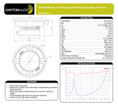
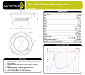
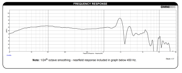
@wg_ski Woofer is Dayton Audio RSS315HO-44 .
two variants , 4 ohm and DVC
"
84db sensibility not so much.
the 4ohm version has 90.5db sensibility ( is it because they tested the DVC at 8 ohm 2.5v ? . , and mms 251g - 327g on the 4+4 dual voice coil,
Fs from 21.5 on the DVC up to 26hz on the single coil version.
that much sensibility difference because of the added mass on the cone? or was it on 8ohm wired when tested ?. ( makes sense the Fs is lower on the 327g vs the 251g ) "
Attachments
Going all the way to 500W wouldn’t actually be all that ridiculous here.
What are you using to power the amp? Or have you not bought a transformer yet?
What are you using to power the amp? Or have you not bought a transformer yet?
P = E^2/RFor 3db , going from 500W to 250W would be wise, less heat and " stress" on the woofer.
+-45v DC might be enough for 2 ohm ?.
Note that E will be the RMS value, so multiply by sqrt(2) and add a few volt for saturation voltage. That'll get you pretty close.
Tom
So you have a trafo from a 4 ohm/8 ohm switchable amp…. That is going to sag like crazy. On the lower voltage tap, expect the 40V to drop about 15%. Lose about 3V in the power transistors. About 22V RMS or 240W at 2. 70% efficiency, 65% power factor is 527VA. Or about 20% “overload”. My assumption of about 15% sag is about right here - you get between 10 and 15% at full VA load for most trannies. It will still run very cool because average loading is much less.
Now switch over to the 63V supply. Since you’re already exceeding VA a lot at lighter load it will sag a LOT more. It was sized for dual channel 8 ohm loading, not 4. So you’ll drop some 30%, taking the DC down to 44V. It will be close to fully flywheeling - acting like a choke input filter, which raises the conduction angle and improve power factor. Lose a little more, say 4V in your power transistors now, so 40 volts peak or 28 RMS. Or 400 watts at 2. Efficiency will drop a bit (say 68% - you’re dropping more in saturation and IR in emitter resistors). Power factor is probably closer to 85%. That puts you at 700 VA loading. It’s not going to burn it out since rule of thumb says average current/power draw for class AB under very loud clipping music is right around half of calculated max. But the result is all that sag. Receiver manufacturers KNOW this, and it’s why they take such liberties with transistor SOA.
If you get an 800VA sag will be back down where it should be and you’ll get that 500 watts, and then some. On +/-63V you’d get close to 800 W. If you were targeting 500 you’d want +/-58V raw supply with 600VA or more. At 15% sag it gives you exactly that. Thats a 40-0-40, which will be a smidge higher unloaded.
With the dual tapped transformer there is the opportunity to go H-class. It won’t sag as much due to lower power demand so you might squeeze the 500W out of it. The downside is needing to add power supply commutators, which you may or may not know how to do. And the fact that using those old Tesla transistors is off the table (Since it won’t work with a QC).
So I need a bigger transformer.So you have a trafo from a 4 ohm/8 ohm switchable amp…. That is going to sag like crazy. On the lower voltage tap, expect the 40V to drop about 15%. Lose about 3V in the power transistors. About 22V RMS or 240W at 2. 70% efficiency, 65% power factor is 527VA. Or about 20% “overload”. My assumption of about 15% sag is about right here - you get between 10 and 15% at full VA load for most trannies. It will still run very cool because average loading is much less.
Now switch over to the 63V supply. Since you’re already exceeding VA a lot at lighter load it will sag a LOT more. It was sized for dual channel 8 ohm loading, not 4. So you’ll drop some 30%, taking the DC down to 44V. It will be close to fully flywheeling - acting like a choke input filter, which raises the conduction angle and improve power factor. Lose a little more, say 4V in your power transistors now, so 40 volts peak or 28 RMS. Or 400 watts at 2. Efficiency will drop a bit (say 68% - you’re dropping more in saturation and IR in emitter resistors). Power factor is probably closer to 85%. That puts you at 700 VA loading. It’s not going to burn it out since rule of thumb says average current/power draw for class AB under very loud clipping music is right around half of calculated max. But the result is all that sag. Receiver manufacturers KNOW this, and it’s why they take such liberties with transistor SOA.
If you get an 800VA sag will be back down where it should be and you’ll get that 500 watts, and then some. On +/-63V you’d get close to 800 W. If you were targeting 500 you’d want +/-58V raw supply with 600VA or more. At 15% sag it gives you exactly that. Thats a 40-0-40, which will be a smidge higher unloaded.
With the dual tapped transformer there is the opportunity to go H-class. It won’t sag as much due to lower power demand so you might squeeze the 500W out of it. The downside is needing to add power supply commutators, which you may or may not know how to do. And the fact that using those old Tesla transistors is off the table (Since it won’t work with a QC).
At the cost of a 800 - 1000 VA transformer and maybe a bit more cash I can buy a pre build smps class D amp .
The problem there is needing a +/-48 volt, 22 amp power supply since the length of TIME required at peak currents is significant. That sumbitch will cost a thousand bucks. A five amp supply from Digikey will NOT work well here.... or use a regulated SMPS. No sag there.
Tom
The Mean Well LOP-600-48 could probably do it. It's capable of 900 W peak power. You'd need two of them to form ±48 V. They'll set you back $85/each at Mouser. I realize that 900 W at 48 V is 'only' 18.8 A, but keep in mind that the signal peak above 18.8 A is very brief and that the supply only provides power for half of the sine cycle.
I haven't used the LOP series yet. I've had very good experience with the previous generation, the RPS-series. I use two RPS-400-27 in the Modulus-686 Safe-n-Sane build.
Tom
I haven't used the LOP series yet. I've had very good experience with the previous generation, the RPS-series. I use two RPS-400-27 in the Modulus-686 Safe-n-Sane build.
Tom
I think it was the crown DC300 that used TO-3 drivers, and you had to find a 10MHz+ part or it would oscillate, particularly the CFP3 side. Modern OPs are a lot faster than 2N3773's etc so not such a big problem anymore. But know that CFP are sensitive to device speed. The driver and OP need to be very different so that the OP pole dominates.
Last edited:
With 100+ MHz predrivers, one can use MJ15024 driving multiple MJ15024 (Or modern 2N3773). Old school 800 KHZ outputs, 2 MHz drivers, with 10-20 MHz predrivers in CFP3 no. That does oscillate. And in any case it’s sensitive to power supply impedance.
It works BETTER with MJL3281 driver, but doesn’t fit the TO-3 socket. And 10-50 MHz TO-3’s - even NPN switching types, are almost gone. They’re having to build the Naim clones out of C5200’s or the latest Sanken NPNs nowadays. No more BDY58’s or the 2N equivalents. BUV21/22 are all that’s left, and they’re on the slower side of the spectrum - closer to 10 MHz.
It works BETTER with MJL3281 driver, but doesn’t fit the TO-3 socket. And 10-50 MHz TO-3’s - even NPN switching types, are almost gone. They’re having to build the Naim clones out of C5200’s or the latest Sanken NPNs nowadays. No more BDY58’s or the 2N equivalents. BUV21/22 are all that’s left, and they’re on the slower side of the spectrum - closer to 10 MHz.
I'd definitely want to prototype it before committing to it. But even with a 20 Hz burst, the supply would only see overload for a few milliseconds every 50 ms. With enough local reservoir capacitance in the amp itself I'd think it'd work.100-3KHz voice, probably but I have doubts about repetitive 20-50 ms bursts for sub duty.
Tom
Many of those supplies do not behave well if you go hanging 10,000 uF off of them. The charging currents can get too high and cause the very misbehavior you’re trying to avoid. The only foolproof way is to stay inside the supply’s design envelope and not force it into protect all the time (even if short periods). Then the amp won’t clip early or find a way to die on you after a years use.
- Home
- Amplifiers
- Solid State
- Output Power Transistors as Drivers?