Hi Bonsai,
That Halcro inductor doesn't look like many uH, but I was never good at eye-balling inductance. What do you think? Might it be 1uH?
Cheers,
Bob
I also think it's circa 1 uH - the diameter is quite large.
Udok,
The L's are simply resonating with the C's and this is quite normal - it usually takes place well above the audio band and has nothing to do with amplifier stability.
I agree with Bob et al that ultimately you want a Zobel on the amp output before the output L and one at the speaker terminals.
The L's are simply resonating with the C's and this is quite normal - it usually takes place well above the audio band and has nothing to do with amplifier stability.
I agree with Bob et al that ultimately you want a Zobel on the amp output before the output L and one at the speaker terminals.
@Bob,
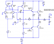
My apologies, I forgot to mention that the OPS is a class-A self-bias design, hence it always runs in class-A (100W/8R as shown in the schematic). Only when pushed hard (>rated class-A output power) it enters class-B territory by means of a different mechanism that modulates the OPS input transistors. The THD hits a proverbial brick wall at that point.
Hi SSassen,
Thanks for the clarification. Nice performance!
Cheers,
Bob
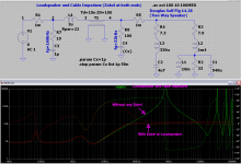
The next picture shows the influence of the R-C Zobel network.
Without the Zobel R-C the line input impedance is capacitive above 600 kHz.
This is critical, because in this region the current gain (beta) of the emitter follower output transistors is falling with 6 dB/octave.
A capacitive load is transformed to a negative resistance at the base. This can lead to oscillations. A R-C at the base, a base stopper, or a R-C at the output can help to stabilize the emitter follower.
A slow output transistor has a Ft of 5 Mhz and a Beta0 of 25. Beta is falling
above 5 Mhz / 25 = 200 kHz and is 1 at 5 Mhz. In this region transistor current
gain beta is Beta0/(j*2*pi*f).
The Zobel R-C is resistive at this frequencies and dampens oscillations.
It is remarkable that this has nothing to do with global feedback stability.
R-Udo
Nice work!
You might also want to try a Zobel at the loudspeaker end. Maybe try something like 100 ohms and 0.05uF in series. This will terminate the line in its characteristic impedance at high frequencies.
Cheers,
Bob
I'm curious how many people actually measure their inductors. I've seen an awful lot of published schematics where the inductor is described by turns on a resistor body or somebody maybe guessed at the value based on what everybody else published. Personally, I've needed well over 2 uH for complete stability with all loads on several amps. IMO, too high, but instability is the greater evil.
Conrad, it will also be related to your overall loop comp and where the ULGF is located - see the pdf I posted above.
Nice work!
You might also want to try a Zobel at the loudspeaker end. Maybe try something like 100 ohms and 0.05uF in series. This will terminate the line in its characteristic impedance at high frequencies.
Cheers,
Bob
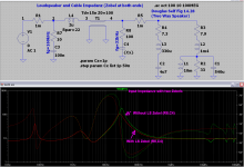
The Zobel at the loudspeaker end works similar to the one at the amp end.
The terminated transmission line behaves like a 100 Ohm Resistor, which is in parallel to the loudspeaker impedance.
Above 32 kHz the amp is seeing a 100 Ohm Resistor. 32kHz may be too low as it has a measureable effect on impedanze (phase).
For audio the loudspeaker and crossover impedance is maybe enough to terminate the "transmission line".
Problem (or Oportunity to earn money🙂): You must provide a "special" loudspeaker cable with your amp.
The second picuture shows the impedanz with both zobels in place. You clearly see: One is enough...
R-Udo
Attachments
Udok,
The L's are simply resonating with the C's and this is quite normal - it usually takes place well above the audio band and has nothing to do with amplifier stability.
I agree with Bob et al that ultimately you want a Zobel on the amp output before the output L and one at the speaker terminals.
And the result is that the emitter impedance is capacitive above the resonance frequency (600 kHz in this simulation).
This is the region where the current gain of the output transistor is falling beta=Beta0/(j*w)
The capacitance at the emitter is transformed to a negative resistance at the base.
The emitter follower is getting into oscillation, if the driver resistance is too low to compensate the negative resistance. This is the reason a base stopper is simetimes used to make the driver resistance higher.
The output transistor has still a lot of current gain above audio frequencies and below its transit frequency.
R-Udo
ok - I see your point. I agree on the base stopper and use 4.7 Ohms (i have used 3.3 as well successfully)
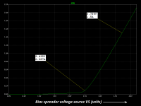
Why didn't you set V5 to 3.726 volts per the plot below?Here are the sims I mentioned showing capacitive load and output inductor combos.
_
Attachments
@moderators,
Can you please move the ExtremA related posts into the ExtremA thread? Apologies to the folks stopping by to learn more about the pros and cons of output inductors in amplifiers.
Can you please move the ExtremA related posts into the ExtremA thread? Apologies to the folks stopping by to learn more about the pros and cons of output inductors in amplifiers.
Why didn't you set V5 to 3.726 volts per the plot below?
_
. . . It's a class AB amp Mark.
.................making things work well only for bench testing 'cause the Ls of any speaker cable is >1uH. ....................
What needs to be done which will make the EF devices unconditionally stable withOut additional Ls in series with the speaker cable/spkr? ..............
Naim's philosophy of only using their high inductance speaker cable in lieu of an internal output inductor was slated by the audio press.................... I think some designers rely just on the speaker cable L. ..........................
Few others do it using specified cable inductance.
That is probably due to the unknown stability effects and resulting bad press, when users and/or retailers fit random cables in attempts to "tune the sound quality".
Yes, I read about Naims giving problems with some cables. I just think that is so unnecessary when the correct engineering solution is well documented, tried and tested.
I agree, there is no guessing at how badly behaved the customer could be in "tuning" by ear.
But I can also accept Naim's philosophy where they move the inductor from inside to outside the chassis.
It is PERFECTLY valid and it WORKS when the customer does what the manufacturer tells them what to do to get designed performance.
But I can also accept Naim's philosophy where they move the inductor from inside to outside the chassis.
It is PERFECTLY valid and it WORKS when the customer does what the manufacturer tells them what to do to get designed performance.
I was going to mention the Naim cable business, but i see it's already been posted !
Sure i expect it works, but it means people are Forced to buy Naim cable, or pay a premium if it's included. Which prevents people from using good ol'e nice price cable 🙁
Quite frankly, i'm amazed that this is still being debated, after all these years. I would have thought there wasn't much mystery etc left ? Obviously there is !
- Status
- Not open for further replies.
- Home
- Amplifiers
- Solid State
- Output inductor in power amps - pro and con