The only difference between TPC and TMC is where the resistor is connected to. Connecting the resistor to the output, what is being referred to as OIC, is slightly better, else it is the same.
TPC vs. TMC has been discussed before BTW:
While being very similar, TMC offers higher performance due to inclusion of the output stage.
Once again, wanted to find these posts and threads by a title search rather than digging for them.
EDIT: This thread was intended to make it easier to find posts on the subject but I'm having to fix the links again.
This time I'm providing the post # so that if the links break again one can search by post #.
I searched on Megajocke's posts and found that his analysis is now on page 61, half of the last link to page 122,
so perhaps posts per page have doubled.
TMC is a derivative/improvement on Cherry's Miller inclusive compensation (or Miller output inclusive) that was first described...
- PB2
- Replies: 55
- Forum: Solid State

Exactly. It’s that extra little bit of error correction through the semi-local feedback I found attractive.
I show what is possible in https://www.diyaudio.com/community/threads/tpc-vs-tmc-vs-pure-cherry.235188/
Though the amp(s) in that thread are virtual, I've built and tested similarly amps in Jurassic times (1990?) with similar results ... especially the 20kHz full power THD residuals
Though the amp(s) in that thread are virtual, I've built and tested similarly amps in Jurassic times (1990?) with similar results ... especially the 20kHz full power THD residuals
TMC is totally worth considering and offers some advantages over TPC.
It would be easy to add both resistor options to a PCB design to have a fallback.
Removing the resistor would be the fallback to plain Miller worst case.
I once built an amplifier with TPC, and performance was very good, as far as I could measure.
The amplifier topology required the resistor goes to the rail for good PSRR, else I might have considered TMC instead.
However, I believe there were issues with stability in some cases (not sure) and I reduced the aggressiveness of the compensation, i.e. reduced the capacitor ratio, and increased the resistor value. The presumed instability was around the closed loop gain peak frequency BTW, hence it is plausible that there could be a risk. Has anybody else observed any stability issues at the closed loop gain peak frequency with TPC or TMC?
In simulation, there was good margin, but this is small signal only, and reality is always a different story.
Does anybody know whether TMC shows the same amount of closed loop gain peaking like TPC?
While being so similar, they are still slightly different.
This certainly has been discussed before, likely multiple times even.
I can answer that question for you!
TMC:


TPC:


The THD also increases a hair with TPC, but it's only about 10PPM difference.
Then there's the OLG.
TMC

TPC:

I doubt that it makes any difference in terms of real performance, but I'm still a TMC fanboy! 🙂
TMC:
TPC:
The THD also increases a hair with TPC, but it's only about 10PPM difference.
Then there's the OLG.
TMC
TPC:
I doubt that it makes any difference in terms of real performance, but I'm still a TMC fanboy! 🙂
also worth checking out is astx's huge thread https://www.diyaudio.com/community/...ance-class-ab-power-amp-200w8r-400w4r.235194/
The important bits are my earlier posts there when his earlier SA201x versions responded correctly to my SPICE world suggestions in 'real life'. As its performance increased, it got to a stage when this no longer held. But the earlier problems encountered, and their solutions give you an idea of the work needed to get excellent performance from a power amp.
I don't think 'pure Cherry' is any more difficult to get stable as other compensastion schemes (including the usual plain Miller at the VAS) but I'm biased. Done properly, 'pure Cherry' gives a HUGE advantage in HF THD
There is no peaking (closed loop) with TMC, as #27 shows, if you keep R52, R53 the same ratio as C6, C24.Does anybody know whether TMC shows the same amount of closed loop gain peaking like TPC?
This not an apples to apples comparison.
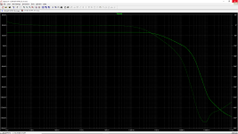
What you call TMC has a 1:1 capacitor ratio and it shows in the OLG plot.
TPC shows the steep roll-off as expected, but your TMC has shallow roll-off and looks like plain Miller compensation because of the capacitor ratio.
What I mean with steep roll-off: In your example TPC has 85dB OLG at 1kHz and 45dB OLG at 10kHz, while TMC has only 60dB at 1kHz and 40dB at 10kHz.
The idea behind the multi-pole compensation is to increase the feedback ratio, i.e. OLG minus CLG. The more OLG at given frequency, the higher the feedback ratio, means the better the ability to retain in control of the amplifier. Given the CLG is 25dB, TPC offers 60dB control at 1kHz and 20dB at 10kHz. Your TMC example (which is not proper TMC by the way), has only 35dB at 1kHz and 15dB at 10kHz.
For an apples to apples comparison you would need to make the capacitors equal in both TPC and TMC.
And the additional resistor that forms a voltage divider with the one connected to the output is also something I haven't seen anywhere before. Where does it come from and what is the idea behind?
You may want to read this:
https://www.researchgate.net/public...-Pole_Compensation_in_Linear_Audio_Amplifiers
https://www.researchgate.net/public...-Pole_Compensation_in_Linear_Audio_Amplifiers
Answering my own question:Does anybody know whether TMC shows the same amount of closed loop gain peaking like TPC?
I use a simulator for this, but you can calculate it as well. Start off by Miller compensating the amp for 70-90 degrees phase margin at the unity loop gain frequency (ULGF). This will usually be between 1MHz and 2 MHz in a bipolar amp using modern sustained beta output devices EF2 or EF3. Once that is done, split the comp cap into two parts. The cap going to the base of the VAS stage keeps the same value. Make the second cap going to the VAS output 2x that of the first cap. Now you have to calculate the resistor part. Use R = f/2*Pi*2c where c is the value of the Miller cap and F is 50...
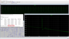
Close loop gain (no peaking).My simulation of CFA amplifier with OITPC compensation. This is without any error corrector at output. Power supply is 35VDC.
Attachments
- Home
- Amplifiers
- Solid State
- Output inclusive compensation - What are the pitfalls?