Could somebody help me with this problem, I'm just wondering what the output impedance is for the circuit beneath.
I have tried to find the formula for the output impedance, but I don't know if it's correct.
the formula I found is:
Zout= Rk || (rp+Ra+u*Rk)
or (Rk*(rp+Ra+u*Rk)) / (Rk+rp+Ra+u*Rk)
I have tried to find the formula for the output impedance, but I don't know if it's correct.
the formula I found is:
Zout= Rk || (rp+Ra+u*Rk)
or (Rk*(rp+Ra+u*Rk)) / (Rk+rp+Ra+u*Rk)
Attachments
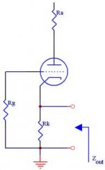
Zout = Rk // [(Ra+ra)/(u+1)]
To put it in words, looking up into the anode, all resistances are divided by a factor of (u+1), and that little lot is in parallel with your cathode bias resistor.
The equation you quoted would imply that loading a cathode follower with a constant current sink insted of a cathode resistor would significantly increase its output resistance.
Zo AT THE CATHODE.
Hi,
The easiest way is:
Output impedance (cathode):
Rk' = (Rl+ra)/(mu+1)
Rout = Rk'||Rk
Where:
Rp = the plate resistor
Rl = the load resistance, or the input resistance of the next stage
Ra = the total load resistance, which is Rp in parallel with the input resistance of the next stage, Rl. If there is no Rl, Ra = Rp.
ra = the internal plate resistance of the tube
mu = the mu of the tube
Keep in mind this for a bypassed Rk.
Cheers,")
Hi,
The easiest way is:
Output impedance (cathode):
Rk' = (Rl+ra)/(mu+1)
Rout = Rk'||Rk
Where:
Rp = the plate resistor
Rl = the load resistance, or the input resistance of the next stage
Ra = the total load resistance, which is Rp in parallel with the input resistance of the next stage, Rl. If there is no Rl, Ra = Rp.
ra = the internal plate resistance of the tube
mu = the mu of the tube
Keep in mind this for a bypassed Rk.
Cheers,
Bypassed Rk?
Hi,
Meaning : cathode resistor bypassed with a capacitor.
Should have clarified that.
For the unbypassed common cathode circuit you can use this:
Rout = [(Ra + ra)/(mu + 1) * Rk] / [(Ra + ra)/(mu + 1) + Rk]
Where:
Rk = the cathode resistor
Ra = the total load resistance, which is Rp in parallel with the input resistance of the next stage, Rl. If there is no Rl, Ra = Rp.
ra = the internal plate resistance of the tube
mu = the mu of the tube
Cheers,
I SEE.
Hi,
Sorry if I got anyone confused here.
Output impedance (cathode):
Rk' = (Rl+ra)/(mu+1)
Rout = Rk'||Rk
Actually this is the output impedance calculated for a common cathode stage,signal is of course taken from the plate,cathode R is bypassed.
Output impedance (plate):
Rout = (ra * Rp)/(ra + Rp)
Hope this sets it straight.
Cheers,
The complicated way, of course, would be to graph operation, determine grid drive for output, then add output voltage to input voltage as NFB, and calculating Zo based on Rp, Rl and amount of NFB applied.
No doubt those equations simplify all this into a single operation...
Tim "but I like the scenic route!"
No doubt those equations simplify all this into a single operation...
Tim "but I like the scenic route!"
- Status
- This old topic is closed. If you want to reopen this topic, contact a moderator using the "Report Post" button.
- Home
- Amplifiers
- Tubes / Valves
- Output impedance