1A bias gives 8W into 4 ohms with linear class A. This is a class AB amplifier. Your measurements are showing the effects of non-linearity.
Ed
Ed
But, what nonlinearity?
I was injecting only 1 Arms into output. I have to inject over 1.41 Arms to push output stage out of class A. Still, distortion at 20 W/4Ω (0.002%) indicates insignificant nonlinearity in class AB.
I was injecting only 1 Arms into output. I have to inject over 1.41 Arms to push output stage out of class A. Still, distortion at 20 W/4Ω (0.002%) indicates insignificant nonlinearity in class AB.
You are measuring a difference in output impedance when:
The difference implies non-linearity. You are measuring the amplifier's distortion in an indirect way.
Ed
- The output is around zero volts (current injection method)
- The output is around some number of volts (two resistors method)
The difference implies non-linearity. You are measuring the amplifier's distortion in an indirect way.
Ed
I was wrong when I stated that the maximum error with the "wrong" method was bounded: it can be much larger in fact.
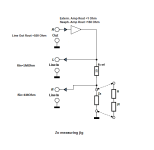
This sim illustrates the problem:

It shows three situations: Zout=0, Zout=0.8ohm reactive and Zout=0.8ohm resistive.
Everything is normalized to 1V.
With the resistive load, the loss is close to 1/11th as expected for 0.8ohm, but for the 12.7µ (|0.8ohm| too, but inductive), the drop is 10 times smaller, meaning the computed impedance would be ~0.08ohm, ten times smaller than reality.
This example is somewhat caricatural, but not that much: most amplifiers have a heavily inductive output impedance, for a number of reasons. Tube amplifiers have an output transformer and its inevitable leakage inductance associated, and solid state amplifiers normally rely on a strong NFB, which also results in a synthetic inductive output.
Good tube amplifiers have both the transformer and the synthetic inductance.
The only amplifiers (almost) immune to that are Pass-like: direct output and zero FB, but they are oddities
This sim illustrates the problem:
It shows three situations: Zout=0, Zout=0.8ohm reactive and Zout=0.8ohm resistive.
Everything is normalized to 1V.
With the resistive load, the loss is close to 1/11th as expected for 0.8ohm, but for the 12.7µ (|0.8ohm| too, but inductive), the drop is 10 times smaller, meaning the computed impedance would be ~0.08ohm, ten times smaller than reality.
This example is somewhat caricatural, but not that much: most amplifiers have a heavily inductive output impedance, for a number of reasons. Tube amplifiers have an output transformer and its inevitable leakage inductance associated, and solid state amplifiers normally rely on a strong NFB, which also results in a synthetic inductive output.
Good tube amplifiers have both the transformer and the synthetic inductance.
The only amplifiers (almost) immune to that are Pass-like: direct output and zero FB, but they are oddities
Last edited:

One of those truly 😳 moments.
If asked, I would bet my salary that equivalent reactive and pure resistive impedances would provide the same voltage drop. Answer is probably in U/I phase shift.
Yes, first amplifier where results align, is direct output with no NFB.
Second one is direct output but large NFB. It has 30 cm wires (2x 15 cm) at output with some 150 nH inductance. Your explanation reveals how that inductance effect can virtually disappear while loading amplifier output.
Using LTSpice and amplifier output impedance as 2 mΩ and wires impedance as 3 mΩ + 150 nH per channel, I got correct behavior similar as measured for resistive loading and current injection from one channel to another. 👍
Thank you.
Beg to differ, I see 10's of % differences in the LF area, that's not a good match at all.Results from both methods match very well.
I would not be happy with such measurements.
Jan
You forget that not everyone has professional lab equipment at disposal. Differences are likely measurement errors and tolerances. If I would repeat every measurement 10 times and use averaging (not simply 10 averages at one moment), there would be less difference, if any.
I made several measurements on each amplifier under slightly different parameters. Results are close enough to confirm that there was a question to be answered.
I made several measurements on each amplifier under slightly different parameters. Results are close enough to confirm that there was a question to be answered.
Ah, slapping my forehead again.
Jan, you have knowledge, equipment, amplifiers …
Do you have time to take measurements under better conditions than mine, to confirm or deny what was determined so far?
Jan, you have knowledge, equipment, amplifiers …
Do you have time to take measurements under better conditions than mine, to confirm or deny what was determined so far?
I do not intend to. I am in no way belittling your efforts, just the opposite, I appreciate it, and I understand that not everyone has state of the art equipment.
But you need to be honest to yourself. If you see results that deviate as much as they do, your conclusion should be that something isn't right.
An output impedance cannot be 6 ohms and 10 ohms at the same time, and if it looks like that in two difference measurements, it is not a good match.
Personally, I would be unhappy and not stop until I figured out what's going on. But that's just me 😎
Jan
Answer to as why one measurement at 500 Hz resulted with 6 mOhm and another with 8 mOhm is known. As said, measurement errors and tolerances. While measuring below 10 mOhm, method with current injection is more precise, because of much higher measurement resolution. Method with 2 resistors has to deal with only 20 mV relative voltage change (jumping several mV) at 6 Vrms nominal level. Error is easily 30% and that is still irrelevant to the main question:
So far it looks that NFB or no NFB is not a factor. Only that at very low impedances change toward higher frequency is not obscured.
impedance of amplifier with NFB is not the same for sourcing and sinking current or for acting as voltage and current source vs. acting as load or current sink.
So far it looks that NFB or no NFB is not a factor. Only that at very low impedances change toward higher frequency is not obscured.
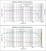
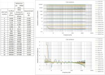
For Zo measurements, I use a soundcard with high input impedance and an external amplifier if the DUT is of low Zo (when the amplifier DUT is a stereo unit, I use one channel to drive the output of the other).
Drive level doesn't change the meas. result, as long as S/N ratio is adequate and soundcard input does not overload.
I test the validity of measurements with a set of test resistors.
Good results for a measurement range at least two decades higher and lower from the Rref
I use REW to take the measurements, then export data to Excel
George
Attachments
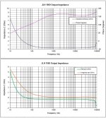

Erratum.
On third attachment (JLH 1969), the real and imaginary components of Zo have been swapped.
George
On third attachment (JLH 1969), the real and imaginary components of Zo have been swapped.
George
In any event, you "have to" (wife says) do a calibration run with a known very low inductance resistor "OPEN, SHORT, Cal LOAD", download to Excel and engineering math magic have a calibration file and "sanity test" for measurement of an actual active load.
My low inductance resistor is 1210 for passive component testing.
My low inductance resistor is 1210 for passive component testing.
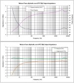
Yes, this cal procedure (Open, Short, Reference cal) is done within REW.
Selection of 'Reference cal' (for REW) and 'R ref' (for measuring jig) is easy when measurement span is not larger than 3 decades, as is the case with Amp Zo.
Things get harder when measurement span increases. Below verification results with 18 test resistors (for measuring a 24 tap multi k turns AVC).
Still good results
George
Attachments

Assuming you get an accurate measurement of the output impedance, an amp without feedback will give you a reflection of the plate curve and an amp with feedback will reflect the closed loop response. Neither of these is the best load for your amplifier, if that's what you care about. I would measure the clipping power over a range of loads, bearing in mind that the lack of a load, ie high impedance is a threat of arcing, so I would not go above 16 Ohms. If this were a solid-state amp, then a rational lower limit would also be wise. The way you measure the impedance depends on why you want to know.
Last edited:
Not getting inside a cats and dogs fight 😊 which this thread is beginning to resemble 😉 but:
1) a Tube amp does not necessarily die a violent death if unloaded ... as long as it is far away from clipping and the ugly switching into an inductive load it entails.
2) my personal experience, back in 1972 go figure, when I was trying to develop an SS guitar amp with a somewhat closer to tubes sound included (among other experiments) driving a Twin reverb amp output into its normal 4 ohm load to about 4V RMS and then removing load.
Voltage rose to about 8 V RMS
Then I deduced damping was about 1 and designed a mixed feedback network to do thye same.
3) back to the main point: at lowish controlled levels, Tube Amps can be run unloaded for measurement.
"But... but .... unloaded OTs behave different!
They behave like a weird mix of inductors, caps and resistors!
To boot, non-linear!"
Yup, and that´s the point.
OTs are always in the Audio path, meaning their elements too.
No big deal IF you include those in the equations.
"But I want just the simple straightforward nominal impedance ratio!!"
Cool, just measure at 1kHz and use the numbers you find.
At midband frequencies all weird elements (serial loss inductance, parallel LF inductance, parasitic capacitance, extreme low frequency non-linearity or saturation, HF attenuation by excessive self capacitance, LC resonances, etc.) will typically have a minimal effect and can be safely ignored.
Unless OCD hits hard that day ;
- Home
- Amplifiers
- Tubes / Valves
- Output impedance measurement - without load?