Maybe because one has everything ready? Zout in tube amps will be hardly small. People using tons of GRND feedback with tube amps you count them with your fingers, I think.Why would you opt for a more complicated method, which happens to be also inferior?
If Zout is really small, heavily non-linear and heavily inductive, the error will be much larger than 10%.
The subject has already been discussed at length, here for example:
https://www.diyaudio.com/community/threads/measuring-power-amp-output-impedance.254341/post-3885135
yes, tube amps have low damping factors compared to SS amps...ergo, output impedance in the 2 ohms or more..
Last edited:
Sure, but the impedance has a non-negligible inductive component which will degrade the accuracy, and more importantly, the "correct" method is easier, simpler and requires no calculations or multiple loads.
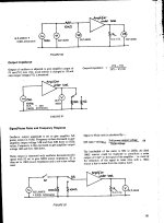
If you test a stereo amplifier, short the input of the channel you want to test, connect a 4.7 or 8.2 ohm resistor between the outputs, apply the test signal to the auxiliary amplifier and adjust the amplitude to read 4.7V or 8.2V across the resistor. Then connect the voltmeter between GND and the output you test: the volts reading will be the output impedance, directly, without calculations: for example, 0.6V means an impedance of 0.6 ohm. Quick, easy and accurate even if the impedance is non-purely resistive or non-linear
If you test a stereo amplifier, short the input of the channel you want to test, connect a 4.7 or 8.2 ohm resistor between the outputs, apply the test signal to the auxiliary amplifier and adjust the amplitude to read 4.7V or 8.2V across the resistor. Then connect the voltmeter between GND and the output you test: the volts reading will be the output impedance, directly, without calculations: for example, 0.6V means an impedance of 0.6 ohm. Quick, easy and accurate even if the impedance is non-purely resistive or non-linear

Whatever you like. It doesn't make any practical difference. Damping fator of 2 or 3 is the same in practice, the ideal speakers for DF=2 will remain ideal for DF=3. Same for non ideal speakers.
You meant to say "infinite" (i.e. open).It's not necessary to have no-load and load. You only need two different loads to calculate, one does not have to be zero.
In fact, it is better not to use a zero load because zero load is a sort of special case and the calculation can be less accurate.
Jan
Good idea. I just added extra load (less resistance). Never thought of raising the load, too and then repeating the test.irrc, "Dogstar" built a high power tube amp with 100ohm resistor, permanently connected to the speaker output jacks, i suspect that the reason was to avoid the amp being played without a speaker connected, in my case i use 10ohm 3 watt resistor in series with a 0.01ufd cap to avoid such problems...
Sorry Jan, I thought I did, but they are all the' LOAD / NO LOAD' kind, nothing with half load.Do you have the calculations available?
Jan
Anyway, I did the measurements, I got 1.6V with 9,4 Ohm and 0.6V with 4.7 Ohm.
With transistors you could use even the load/no load test
With tubes is more complicated as changing the output load resistance will change the load of the tubes in the primary so the power/voltage itself .
The 2 points must be close enough not to disturb much the Ra of the tubes , so you need a precise AC multimeter .
A tube amplifier is not a constant AC voltage source in the true meaning ...
Last edited:
While I like LV's idea, but two amps (channels) that are unstable without a load are probably also unstable when connected together through a load or not. I would drive the amp into a (~8 Ohm) load at low level, and then measure the short circuit current (with the same signal). Many tube amps have shorting speaker jacks to prevent arcing. But the characteristic output impedance and the maximum power output impedance may not be the same thing.
It would be a problem if the two amplifiers were driven synchronously, from the same source: each would see an ~∞ load. When a channel is inactive, it presents a complex but low load to the other amplifier; a speaker generally has a much weirder behaviour, yet the amplifier can (or should) drive it.While I like LV's idea, but two amps (channels) that are unstable without a load are probably also unstable when connected together through a load or not
Of course, you could always find an example of an amplifier behaving in a pathological manner, but a) it should be corrected and b) it can be tested with a lab amplifier having a <0.01ohm impedance.
A typical solid-state amplifier will fit the bill and will not mind if the AUT is insanely unstable
BTW, it is not "my idea" (I would love it), it is standard practice since modern amplifiers can have impedances in the milliohm range, which is completely unworkable with the two loads method.
Another advantage of this method is that you can look at aspects of the residue other than its mere scalar magnitude: non-linearity, phase, etc. which all provide insights into the behaviour of the AUT, not just the impedance.
A word of caution though: this method shouldn't be used with current-mode amplifiers, for obvious reasons
Last edited:
So, that's easy then. First, calculate the two output currents Vout/Rload. The difference between those two currents is the delta-current.Sorry Jan, I thought I did, but they are all the' LOAD / NO LOAD' kind, nothing with half load.
Anyway, I did the measurements, I got 1.6V with 9,4 Ohm and 0.6V with 4.7 Ohm.
You also know the delta-voltage, that's the difference between the two output voltages.
Then Zout = delta-Vout/delta-I. Easypeasy.
Jan
Thank you very much Jan, I wish I had had teachers like you in school.
So: 1,6V over 9,4 Ohm : 0,170 A
0,6V over 4,7 Ohm: 0,127 A
Delta V = 1V
Delta I = 0,043 A
1 / 0,043 = 23,25 Ohm
I have no idea whether that's good or bad... Low is good I think, but how little is low?
So: 1,6V over 9,4 Ohm : 0,170 A
0,6V over 4,7 Ohm: 0,127 A
Delta V = 1V
Delta I = 0,043 A
1 / 0,043 = 23,25 Ohm
I have no idea whether that's good or bad... Low is good I think, but how little is low?
You can relate it to the damping factor, which is the ratio of load impedance to output impedance.
Say you have an 8 ohms load and an output Z of 4 ohms, the damping factor is 8 / 4 = 2.
You normally want a high damping factor to avoid that the impedance variations of the load (speaker) impact the system frequency response.
Generally, a damping factor of 10 to 20 is sufficient.
In your case, the damping factor (with 8 ohms load) is 8/23.25 = ~ 0.3 which is quite low.
I would look for the reason of the highish Zout.
Is this a single ended tube amp? No feedback?
Jan
As I said , it is useless calculating a damping factor with normal/double Raa ... maybe 0,5ohm step between measurements or even less .
You should keep Raa relatively the same otherwise the measurements have no meaning , thats't not the output resistance , it's another operating point for tubes . If somebody else will measure at half/triple Raa the results would be completly different .
A tube amplifier is not like a transistor amplifier .
And even for a transistor amplifier I doubt that such big load changes would give you always the true exact damping factor . If it is for 8ohm you should measure in that region
Last edited:
For hifi you would like less than 10 ohms I would say, your 23,25 ohms would make it a nice electric guitar amp!I have no idea whether that's good or bad... Low is good I think, but how little is low?
It also matters a lot what speakers you are driving.
@Miniwatt using the spreadsheet provided by @tombo56 in post 13 and the numbers you provided, your amp has a -23.5 ohm output resistance. I did the math myself with voltage dividers and got the same result. For any positive output impedance less than infinity, the voltage across load should increase for increased load impedance, while load current will decrease. In your case, both current and voltage increase with increasing load impedance.
- Home
- Amplifiers
- Tubes / Valves
- Output impedance measurement - without load?