Try and follow why 🙂
Can you see that a DC coupled amp can supply a perfect squarewave all the way down to DC if required ?
You reduce the input frequency 10hz, 9 hz and so on all the way down to DC and the DC coupled amp produces a perfect output across the load.
The load current flows from the amp output to the star. Yes 🙂
If we put a 1000uf cap in series with the amplifier output and connect the load to the other end of the cap the amp now does not reproduce a perfect squarewave across the load as frequency goes down. Do you follow that ? That is because that cap is in series with the load.
If the PSU caps were similarly "in series" with the load a similar effect would be seen. The output would not go down to DC.
If you don't agree say so 🙂
What about the transformer as a path for DC. Well you can run the amp from the caps for a few moments by disconnecting the transformer... so it's not flowing there.
Yes, you demonstrate in an unquestionable way the impossibility.
Which made me look more deeply to the thing...
Now i am ashamed of having been so stubborn.
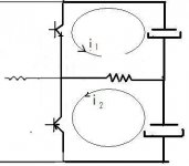
Simply looking at the way output and psu are connected, it is evident caps are not serial connected to the load. They are used as generators feeding the load through variable resistors (the output transistors).This, in a bridge arrangement
I have to apologise to everyone here for the time consuming.
Thank you very much, Mooly, to have been so patient.
Attachments
Last edited:
Member
Joined 2009
Paid Member
Yes, this is how I see it, both on paper and in my sims - the way in which the signal flows through the output caps.
Yes, this is how I see it, both on paper and in my sims - the way in which the signal flows through the output caps.
The generator doesn't care this flow as long as it is a generator.
The bigger the cap/transfo the stiffer is the generator.
Last edited:
Please post a related schematic link to the JLH PSU you mentioned.
It's not public, it's in one of his books. Basically, it's an electronic fuse. In case of multi-rail PSU more than one would be needed.
Of course is not 100% safe as a relay close to the speakers terminals, but i prefer to take the risk rather than using one.
I think we already covered that point... if it's any kind of amp other than a buffer it will use feedback.
Can you show me a design you think has no global feedback, other than a buffer ?
I must have missed it somehow...
Would you define the Pass BA1 a buffer?
If we put a 1000uf cap in series with the amplifier output and connect the load to the other end of the cap the amp now does not reproduce a perfect squarewave across the load as frequency goes down. Do you follow that ? That is because that cap is in series with the load.
If the PSU caps were similarly "in series" with the load a similar effect would be seen. The output would not go down to DC.
If you don't agree say so 🙂
I do agree 🙂
Member
Joined 2009
Paid Member
The generator doesn't care this flow as long as it is a generator.
The bigger the cap/transfo the stiffer is the generator.
I agree, the PSU doesn't care.
But what I was trying to say a few pages back is that the signal does flow through the PSU capacitors, so I would expect that this would have some impact on the sound ?
Member
Joined 2009
Paid Member
Very little impact due to the amps PSRR.
It's the 'very little' we're worried about. I realize that a dc blocking output cap only has a very little affect on the sound, but now that I've heard it I wonder about any cap that is part of the circuit that the load current flows through. Are the PSU caps able to affect the sound equally to that of the dc output cap ?
I would,nt say equally as in a single supply amp the current flows both ways into the cap. It is serial connected to the load during the upper half wave and parallel connected during the lower half wave.
In that way it is different.
In that way it is different.
I have to apologise to everyone here for the time consuming.
Thank you very much, Mooly, to have been so patient.
You're welcome 🙂
what's so hard about making the function/circuit position distinction and applying some #
psu Cap errors are divided by the amplifier circuit psrr - which can be really big - >120 dB at low frequencies - a good thing since we usually have 120 Hz rectifier ripple of several V - successful audio amps do not have audible ps ripple noise in their outputs - can't you see that "errors" caused by load current flowing in the ps C is in exactly the same place in the circuit and is attenuated by the same big number?
output DC blocking C is outside of the feedback loop and forms a high pass filter/impedance divider with the load = only the ~Zc/Zload attenuation of load current caused error of the output DC blocking C impedance nonlinearity
in high psrr circuits ps C can literally have Millions of times less effect on the audio signal - despite any sloppy heuristics claiming they "are in the signal path"
"load current loop" is not the same as "signal path" - yes there is a "signal" = errror V on the ps Caps due to the load current - but we're not listening to it - its not the "audio signal" which == difference V across the loudspeaker terminals
Last edited:
Member
Joined 2009
Paid Member
It's probably because I'm being thick that I don't get this, but anyhow...
The AC current flow through the load depends on the impedance of the all items that it flows through, each one of them contributing something. The diagram posted earlier showing the AC current flow (in a kind of bridge mode) illustrates this well.
The output devices contribute by varying the current that flows through them in accordance with the input signal, the psu capacitors hopefully do nothing to affect the AC current, but any distortion they do create must therefore affect the AC current flowing through the load.
I'm starting to see that the feedback of the amplifier acts to minimize this impact of the PSU caps on the overall sound because the feedback measures the voltage across the load (without the PSU caps) and the error amplifier compares this with the input signal. It seems that it is the feedback factor that is important. I don't see a role for PSRR here except that it is directly improved by feedback.
A dc blocking output capacitor is usually left out of the feedback network because of a) the desire to use the feedback network for dc-servo and b) the worry about phase shifts causing l.f. oscillations. But if we did include the output dc blocking cap into a feedback loop we may be able to lessen their influence to the same extent as the psu caps.
Am I getting there ??
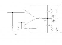
I beg to disagree that the power supply caps are NOT in series with the loudspeaker and don't impart their limitations on the overall sound. The reason for this confusion is the definition of GROUND. You see, ground in an amp or preamp, is really NOT the Earth, but something completely artificial and just called 'ground'. No one can insist that 'ground' is always perfect, in fact, at low and high frequencies, it is usually kind of lousy. Do a little thinking about it and you will see this. Now, for some reason, people here are talking about using output caps in series with a loudspeaker and using a single power supply to power the amp like the Dyna ST120 and the Quad. Many British designers stayed with it, long past its time, but the rest of us saw the ADVANTAGE of taking the output cap and putting it in the power supply, making a +/- supply. Then the 2 caps are in PARALLEL and do double duty, as the low Z series pass for the loudspeaker, and filtering the power supply ripple. This did not come, overnight, and many of us had to think about it for awhile, but we rarely looked back once we switched over to dual supplies. In either case the power supply caps are still significant as the return current from the loudspeaker flows through them.
But if we did include the output dc blocking cap into a feedback loop we may be able to lessen their influence to the same extent as the psu caps.
Either do as Quad does whith their 606 and 909 models.
Attachments
It's the 'very little' we're worried about. I realize that a dc blocking output cap only has a very little affect on the sound, but now that I've heard it I wonder about any cap that is part of the circuit that the load current flows through. Are the PSU caps able to affect the sound equally to that of the dc output cap ?
No, because in an output cap the signal flows through it, PSU caps it does not and it also has the amp PSRR making the effect even smaller.
"load current loop" is not the same as "signal path" - yes there is a "signal" = errror V on the ps Caps due to the load current - but we're not listening to it - its not the "audio signal" which == difference V across the loudspeaker terminals
Exactly! 🙂 Good post.
The output devices contribute by varying the current that flows through them in accordance with the input signal, the psu capacitors hopefully do nothing to affect the AC current, but any distortion they do create must therefore affect the AC current flowing through the load.
What distortion do the PSU caps produce? There is no signal flowing through them. Cap voltage does not really affect the AC current flowing through the load because the amps PSRR applies a massive load of ripple reduction.
Member
Joined 2009
Paid Member
What distortion do the PSU caps produce? There is no signal flowing through them. Cap voltage does not really affect the AC current flowing through the load because the amps PSRR applies a massive load of ripple reduction.
I still believe that the signal does flow through the PSU caps and the PSRR is not relevant except for being a good indicator of feedback factor.
I still believe that the signal does flow through the PSU caps
As there is no other way, let us choose these caps carefully.
About the ESR value, this thread is confusing me...
http://www.diyaudio.com/forums/digital-source/164962-caps-after-regs.html
- Status
- Not open for further replies.
- Home
- Amplifiers
- Solid State
- Output capacitor: subjective and objective views?