I have a Kenwood KA-801 even though it is marked as Trio KA-801 and i cant fix the bias it will start creeping up from 7mV at switch on right up to over 57mV after about ten minutes and starts to warm up then. The bias control is at the lowest point. This is happening on both channels but the right is slightly higher.
What i have done so far is Replace the bias diode and driver transistors with no improvement not checked the output transistors yet but the amp does work fine its the the bias to high.
please if anyone can help
What i have done so far is Replace the bias diode and driver transistors with no improvement not checked the output transistors yet but the amp does work fine its the the bias to high.
please if anyone can help
You mean DC offset at speaker outputs rises with time? Bias is normally used to describe quiescent current through output transistors. If that rises, it's normal for warmup, but should stabilize otherwise thermal runaway. For DC offset - is there a trimpot somewhere on input stage ? That's usually where DC offset is controlled. Some amps don't have offset adjustment and rely on matched differential transistor LTP stage. Then nothing to adjust. But 57mV is barely acceptable DC offset. It's less than a 1mW thermal load on your voice coil so don't worry about it.
output bias should not rise and keep rising as the amplifier warms up.
Most cheap commercial amplifiers use small heatsinks to save money. These require a very low output stage dissipation to prevent overheating. They achieve this by setting up with a very low output bias current.
It looks like the temperature compensator has stopped working.
You need to find it and find out why it is now misbehaving.
Last edited:
first tests for power amplifier are output bias, output Hum+Noise and output offset.57mV is with or without speakers connected
All of these are done with the input shorted and with the speakers disconnected.
It is difficult to debug without the schematic. If there is a trimmer to set the output offset, perhaps it's a bit old? The output offset of 57mV isn't much. Is the heating up severe? Is it different to the past? An amplifier takes a long time to heat up, depending on the size of the heatsinks, but for this sort of power it should take quite a while. I would expect it to heat up a bit.
What I would do is leave it on for > 1 hour, checking it every now and then. If it continues to heat up without settling somewhere, then there's a problem: perhaps biasing diodes aren't thermally connected to the drivers / output stage. If it gets warm, but then settles, that's fine. Even 100mV output offset is acceptable, I guess. It shouldn't get hot (I assume it's not class A).
Then, I would check the quiescent current. While checking that, turn the bias trimmer and if the current changes, then set it to say 50 mA. Remember to turn the bias trimmer slowly.
Most importantly, does it work? In other words, does it amplify sound nicely?
It is the quiescent current that is rising the offset is about -13mV but this starts going more positive as the quiescent current rises.
No speakers attached during measurements,
Quiescent current of 57mV is as high as its been and that probably takes about 15 - 20 mins it really just creeps up very slowly on both channels. It starts to drop a bit when the heatsink heats up and the diode starts to kick in but does not drop much
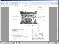
I have attached a schematic and quiescent current adjustment procedure
If the text is not clear i can zoom in and upload again
No speakers attached during measurements,
Quiescent current of 57mV is as high as its been and that probably takes about 15 - 20 mins it really just creeps up very slowly on both channels. It starts to drop a bit when the heatsink heats up and the diode starts to kick in but does not drop much
I have attached a schematic and quiescent current adjustment procedure
If the text is not clear i can zoom in and upload again
Attachments
Replacing driver transistors could be problematic if the circuit has a very limited range of adjustment. A slightly different Vbe due to different manufacturing and doping processes can happen.
Normally a circuit has enough range to swing the bias down to zero and also up to some destructive value. The fact both channels are the same suggests this isn't a 'fault' as such.
It would help to see the output stage circuit details. One thing that a problem like this is NOT, and that is the output transistors.
Has the amp some unknown history ? Has it been modded and worked on in the past ?
Could the rising bias be some form of instability or oscillation due to some circuit changes ?
Just trying to cover all possibilities 🙂
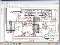
That looks a very fussy arrangement. Shunting the preset with 36 ohms and all.
So it looks like the diode is the sole means of thermal compensation. I suspect this is going to be down to the transistor characteristics being slightly different. Adding a resistor across the diode would bring the bias down, but the value would need to be determined experimentally. Adding anything across the diode is only going to reduce the bias though so no worries of it going to high.
I would also say the bias should be set and re-tweaked when the amp has reached thermal equilibrium. The diagram shows 20ma flowing in one pair of output transistors and that translates to approx 9 millivolts across one of the 0.47 ohm. So 18mv would be across the pair... so the numbers check out.
I think seeing the bias rise as it heats is going to be normal tbh. You need to ensure that its not to high when the amp is up to temperature. That means it will run a bit low from cold but that shouldn't be an issue.
The resistor across the diode sounds a good idea,
I don't think the amp has been modded in anyway as the PCB's underside on both boards look untouched.
I did replaced the driver transistors on one side only as i said on a earlier post just in case they were oscillating and that made no difference.
I found if the driver transistors are sprayed with freeze It 20 the Quiescent current reading drops right down to about 10 - 20mV and then starts slowly creeping up again 😕
That's expected. Vbe for a given Ic has a negative temperature coefficient, so if you cool them down, the same B-E voltage will result in less current flow and hence also less bias for the outputs.I found if the driver transistors are sprayed with freeze It 20 the Quiescent current reading drops right down to about 10 - 20mV and then starts slowly creeping up again 😕
That's also why output stages with TO-92 style driver transistors tend to be no miracles in temperature stability. These cases have high thermal resistance and they are usually mounted away from the main heatsink, so they'll heat up happily when pushed.
BTW, have you checked for oscillation?
Last edited:
Agreed that the slow rise is likely normal. Many amplifier designs are slow to settle to their quiescent (idling) state because of large thermal masses and paths like the heatsink or even air currents slowing the temperature sensor response down - sometimes a lot, like several minutes, as you find. With the cover removed, some won't reach specified bias or settle at all.
The diode sensor is possibly one of those multiple diodes (2-4 diodes in series) which was common in early Japanese designs. You can measure a voltage drop across this to verify it works and even estimate the number of junctions, if ever you need to replace it. Since it is shown detached from the PCB, is it positioned elsewhere or attached to anything, like the heatsink for instance?
As long as the bias can be adjusted to the correct value after waiting until it settles and then re-adjusting slightly as necessary, I still think this will be non-problem since both channels respond similarly.
I think STV-4 diode has 4 junctions. It needs to be in good thermal contact with the heat sink to accomplish anything, hopefully right at the output devices. Sometimes they go bad, but if both channels are the same, they're probably OK. Diodes aren't popular today, but they can work reasonably well. If you have to, a resistor across the diodes might get things down to a reasonable level.
The diode will be a four junction type because it has to bias 4 series vbe junctions, the driver pair and output pairs.
Just to look at this from another perspective...
The circuit shows 0.47 ohm emitter resistors which in turn suggest that the optimal bias would be around 60 milliamps give or take. That would equate to 28 mv per 0.47 ohm or 56mv across a pair.
James... I can't see on the circuit where the test points are located. Are you measuring across a single 0.47 ohm or across a pair (so 0.94 ohms total) ? Its certainly not unknown (in fact its surprisingly common) for service manuals to contain errors.
The 57mv you mentioned earlier would in fact be around the theoretical correct value if you were measuring across a pair of 0.47 ohms.
When you say Bias Diode do you mean D1. Is it bonded to the heatsink? If so did it have thermal conductive paste? Was that paste dried out? You said you replaced it. What did you replace it with? Usually there is some form of thermal feedback to stabilize the quiescent current, be it a thermistor or semiconductor device. It must be both physically and thermally bonded to the heatsink using thermal compound. If it indeed had this but it was dried out it could cause your problem and since both channels exhibit the same fault, seems a good bet.
I measured across the pair of 0.47 ohm = 0.94 ohms in total which is what the manual reads.
What is the purpose of the four small transistors connected to the base of the two driver transistors and the word ASO just above it? It just so happens that the base of these small transistors is also the same place the Quiescent current is measured from, The mystery deepens!
I have tried an SV-04 diode that is known to be good and used that in the kenwood but it just ran up to high so turned off quick.
Those transistors are for protection. When the voltage across either 0.47 ohm reaches at least 0.7 volts then it can be used to turn on a transistor and that transistor (or transistors as here) are then used to 'pull down' the drive voltage thus limiting the current. The two resistors on the base which is R7 and R9 for the top pair form a voltage divider and so allow a bit more than 0.7 volts to be developed before limiting occurs.
ASO... no idea, but the term SOA or safe operating area is common when talking protection of semiconductors.
ASO... no idea, but the term SOA or safe operating area is common when talking protection of semiconductors.
Hi James,
hifiengine.com has the service manual (SM), not just the schematics (looks like you already have it, others might not).
The SM calls for 18mV across two emitter resistors for bias adjustment, for one pair of final transistors.
That, as Mooly suggested initially, is about 20mA across each final transistors.
With the +/-55V rail voltage that is about 4.4W dissipation per channel, so some warming of the cooling fins can be expected.
As for adjusting the bias, first let the amp warm up, let it idle for about 10 minutes without any signal and load, and then adjust the bias as per the manual.
If you think that the STV-4 diode is fine, and you can not reduce the pot any lower to get the voltage into spec, reduce the the resistors in series with the diode/pot combo, R1, R3, to 10 Ohm or so, and readjust.
You could also check R1, R3 resistors if they are within specs. An increase in value could cause the symptoms you are experiencing.
According to the voltages on the schematics, there is about 4mA running through that STV-4 diode. When the diode is out, hook it up to a regulated PS in series with some resistor (~1k) in forward direction, adjust the current to 4mA (with the resistor, and/or the voltage of the PS), and the voltage across STV-4 should be about 4 x 0.6V, or 2.4V, as Mooly suggested. This would tell you if the diode is fine or not.
Mooly:
The test points (you probably found them by now) are at the top edge of the dashed line box drawn around the final amp schematics, where the external final transistors are connected.
Good luck, Peter
Last edited:
- Status
- Not open for further replies.
- Home
- Amplifiers
- Solid State
- Output bias just keep keeps creeping up