hi guys,
excuse for this newbe question, but would know if is possible and how to measure which is the lead of outer foil in caps.
this for case study homework😱
excuse for this newbe question, but would know if is possible and how to measure which is the lead of outer foil in caps.
this for case study homework😱
Measure: wrap around some kitchen aluminium foil and measure capacitance between the foil and each ends. Higher measured vaue belongs to the outer foil.
Empirically: hold the capacitor in your hand and touch each lead to the input of an audio amplifier. Higher hum belongs to the outer foil.
Measure empirically: connect an oscilloscope probe to each leads. Touch the capacitor body with your finger. Higher mains AC signal belongs to the outer foil.
Empirically: hold the capacitor in your hand and touch each lead to the input of an audio amplifier. Higher hum belongs to the outer foil.
Measure empirically: connect an oscilloscope probe to each leads. Touch the capacitor body with your finger. Higher mains AC signal belongs to the outer foil.
isn't a portable oscilloscopeMeasure: wrap around some kitchen aluminium foil and measure capacitance between the foil and each ends. Higher measured vaue belongs to the outer foil.
intresting, i'll try it, but i want test with oscilloscopeEmpirically: hold the capacitor in your hand and touch each lead to the input of an audio amplifier. Higher hum belongs to the outer foil.
don't change nothing with none of my caps....probably my hantek 6022be needs to configured for this type of testing, i hope someone helps meMeasure empirically: connect an oscilloscope probe to each leads. Touch the capacitor body with your finger. Higher mains AC signal belongs to the outer foil.
What if you connect the other lead to the GND of the probe? I will try it myself at home. But outer foil is usually marked on wrapped foil capacitors, and the only reason I can imagine is susceptibility to stray electric field (outer foil should be connected to lower impedance point in the circuit: e.g. signal source, GND, in order not to pick up any noise). A test should also be based on this.
Look at video of film capacitors tests with oscilloscope
Are Your Capacitors Installed Backwards? Build this and find out
and quick test with amplifier
Tone/coupling cap outer foil test - THE EASIEST WAY.
Have a nice day 🙂
Are Your Capacitors Installed Backwards? Build this and find out
and quick test with amplifier
Tone/coupling cap outer foil test - THE EASIEST WAY.
Have a nice day 🙂
For this to work you need the input impedance of the oscilloscope to be similar or smaller in magnitude than the reactance of the capacitor at 50/60Hz. A high impedance input will not show any difference.lcsaszar said:Measure empirically: connect an oscilloscope probe to each leads. Touch the capacitor body with your finger. Higher mains AC signal belongs to the outer foil.
none values don't change also.What if you connect the other lead to the GND of the probe? I will try it myself at home. But outer foil is usually marked on wrapped foil capacitors, and the only reason I can imagine is susceptibility to stray electric field (outer foil should be connected to lower impedance point in the circuit: e.g. signal source, GND, in order not to pick up any noise). A test should also be based on this.
probably i'm newbe and a scheme of the procedure anche settings would be better then 1000 words 😉
too complicated for me 😱Look at video of film capacitors tests with oscilloscope
Are Your Capacitors Installed Backwards? Build this and find out
i don't have guitar amplifier, i'm not just a lucky man 🙂and quick test with amplifier
Tone/coupling cap outer foil test - THE EASIEST WAY.
Have a nice day 🙂
here mine:For this to work you need the input impedance of the oscilloscope to be similar or smaller in magnitude than the reactance of the capacitor at 50/60Hz. A high impedance input will not show any difference.
Qingdao Hantek Electronic Co., Ltd.
Input impedance is 1M. The capacitor would need to be less than around 5nF for the test to work.
oh no!, so there is not any method to do the test on caps i want with that oscilloscope?Input impedance is 1M. The capacitor would need to be less than around 5nF for the test to work.
ops!....i've done measurements without generator....could be this the reason of my faliure ?
what type of generator ?
if yes how must i proceed ?
what type of generator ?
if yes how must i proceed ?
ops!....i've done measurements without generator....could be this the reason of my failure ? what type of generator ?
diypass:
The "generator" is just the static voltage on your fingers touching the capacitor that comes from the electric fields in your environment.
For this to work you need the input impedance of the oscilloscope to be similar or smaller in magnitude than the reactance of the capacitor at 50/60Hz. A high impedance input will not show any difference.
DF96:
Thank you for that post! I never thought about the fact that very high input Z’s on a scope would respond equally, or nearly so, to the very low power noise voltages we are looking for. This would apply even more so to a scope with a typical 10x probe attached (approx. 10MΩ impedance).
Electricians experience the same problem trying to verify power grounds and neutrals when measuring voltage between hot and ground or neutral. With the very high input Z of typical multimeters, they often see full voltage readings even when the ground or neutral does not have a proper connection. This occurs due to capacitive coupling and the better electrician multimeters have a "Low Z" input impedance mode to avoid false or "phantom" voltage readings.
diypass:
To keep your scope’s input impedance less than or equal to the reactance of the capacitor you are testing, you need to know how to calculate capacitive reactance at your country’s power frequency.
Xc = capacitive reactance
π = 3.14
F = 50Hz or 60Hz
C = capacitance in Farads (1 µF = 0.000001 F for example)
Xc = 1/2πFC
Elvee:
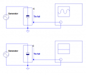
Excellent schematic, thanks for going to the effort. I stole it. 🙂
Last edited:
The fact that the outer foil is difficult to determine except under certain specific circumstances serves to remind us that in most situations we don't need to know which is the outer foil.
The generator is a standard audio or function generator.ops!....i've done measurements without generator....could be this the reason of my faliure ?
what type of generator ?
if yes how must i proceed ?
Ideally, the frequency should be set as high as possible, except that the practical limit depends on the capacitance value and the generator's output impedance.
Function generators generally come in 50 ohm, sine oscillators can be 600 ohm or any other value.
Anyway, 1kHz should be OK in most cases except if you measure really high capacitance ones, like >1µF
PS:
Relying on stray fields caused by the mains frequency is probably one of the worst options: ideally, you should make the test on a ground plane, and use a test frequency visibly different from the mains frequency and its harmonics, to avoid confusions
PPS:
I just remade a sanity check of the method, and the results are completely unambiguous, even on "difficult" cases, like small boxed caps
Last edited:
i tried don't change nothing !!!, why ?The generator is a standard audio or function generator.
Ideally, the frequency should be set as high as possible, except that the practical limit depends on the capacitance value and the generator's output impedance.
Function generators generally come in 50 ohm, sine oscillators can be 600 ohm or any other value.
Anyway, 1kHz should be OK in most cases except if you measure really high capacitance ones, like >1µF
PS:
Relying on stray fields caused by the mains frequency is probably one of the worst options: ideally, you should make the test on a ground plane, and use a test frequency visibly different from the mains frequency and its harmonics, to avoid confusions
PPS:
I just remade a sanity check of the method, and the results are completely unambiguous, even on "difficult" cases, like small boxed caps
Show your setup, indicate the capacitor's value, in short give us all the details: the reason will be immediately apparent, because as I said earlier, the method is extremely robust and reliable, at least when there is indeed an outer foil: if you try to determine a standard ceramic disc capacitor that way, your results will be completely inconclusive for a very good reason....i tried don't change nothing !!!, why ?
What generator do you use?
Can you post a pic of your setup?
3.9µF is already large and if you use a high impedance generator, it will pose problems. With a 50 ohm one, it is still just manageable.
Try setting the test frequency to 100Hz, use a good ground plane and push the scope's sensitivity to the max, it should work
PS:
For a 3.9µF cap, the outer foil side will normally not matter at all, except perhaps in some rare metrology-related instances, so you can happily connect that cap either way, there will be no discernable impact
Last edited:
- Home
- Design & Build
- Equipment & Tools
- Outer foil cap measurement with Hantek 6022BE