tone generator Tolvan Data
setted 100hz , sinusoid
i generate signal by sound card
do you want screen capture ?
could you draw exactly phisical connection ?😱 probably i wrong in connections
setted 100hz , sinusoid
i generate signal by sound card
do you want screen capture ?
could you draw exactly phisical connection ?😱 probably i wrong in connections
¿¿¿¿¿?????? If that seems complicated, then you are not qualified to pass your test.too complicated for me 😱
Pass? ... not even to *take* it.
Out of that video all you need to understand and do is the segment from 8:40 to 12:00 and nothing else.
Still looks difficult? 🙄
EDIT:
At that capacitance value this measurement is irrelevant.capacitor is auricap 3.9uF
At 50Hz it shows around 800 ohm impedance so if diven from a low impedance, following grid will see it too, so minuscule electrostatic hum induced voltage there.
Meaning the tiny shield offered by outer foil actually does nothing from a practical view, it applies to very high impedance circuits (think 1M grid resistors) and small capacitors, so a highish impedance separates plate and grid circuits.
When just 800 ohm join them, "both sides are the same" and (poorly) shielding one or the other becomes irrelevant, since possible induced voltage is almost zero.
Last edited:
Hi,
in my companies office there seems to be quite some electro-smog in the air.
When I connect the legs of a Cap to the scope I can see a small signal sinewave on the display (a 10:1 probe on a LeCroy Waverunner 64Xs with a miniumum sensitivity of 20mV/div ... hence not even overly sensitive).
Simply holding the cap between my fingers increases the amplitude considerably, but differently depending on the orientation of the Cap.
The probe´s test pin is connected to the outer foil when the amplitude is higher and its lower when its connected to the gnd-strap.
jauu
Calvin
btw. it was not too uncommon in earlier (tube) times that a ring was printed on the cap´s casing, marking the outer foil pin.
Calvin, thanks for re-confirming my earlier remarks.
By the way, are there any capacitors using a winding technique where the outer ends of the foils are half-turn apart from each other? Then there won't be "inner" and "outer", both foils will be outer.
By the way, are there any capacitors using a winding technique where the outer ends of the foils are half-turn apart from each other? Then there won't be "inner" and "outer", both foils will be outer.
could explain in a more precise way😱 ?Empirically: hold the capacitor in your hand and touch each lead to the input of an audio amplifier. Higher hum belongs to the outer foil.
thank you
It is difficult to clarify a sentence which already seems extremely clear.
Anyway, for 3.9uF this test is unnecessary. 'Outer foil' is only relevant when the cap has a low enough value that stray capacitance to the outer is not entirely negligible when compared to the cap value. We are speaking nF, not uF.
Anyway, for 3.9uF this test is unnecessary. 'Outer foil' is only relevant when the cap has a low enough value that stray capacitance to the outer is not entirely negligible when compared to the cap value. We are speaking nF, not uF.
they don't usually has an outer foil and cut equally, just connect one lead to the package and it is outer then.
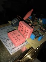
I had hum using this capacitor as input coupling cap.
Reversing this hum was gone.
Outer side is marked in this case.
Reversing this hum was gone.
Outer side is marked in this case.
Attachments
Last edited:
A logical way to test a capacitor foil is to connect one lead to ground, one to a signal, and sense the field around the cap capacitively. Then reverse the connections. Whichever way round has the highest sensed field has the outer foil connected to the signal.
This method will work whatever the capacitance value (so long as the signal generator can drive that capacitance at the frequency used - use a low frequency distiguishable from mains).
But a fairly sensitive high-impedance probe is needed.
This method will work whatever the capacitance value (so long as the signal generator can drive that capacitance at the frequency used - use a low frequency distiguishable from mains).
But a fairly sensitive high-impedance probe is needed.
'Outer foil' is only relevant when the cap has a low enough value that stray capacitance to the outer is not entirely negligible when compared to the cap value. We are speaking nF, not uF.
One likely reason for cap foil orientation in vintage amps was related to the input stage pentode screen bypass cap - a relative elephant amongst other parts, especially when shoe-horned in to a tight chassis. Having that physically large outer surface sitting at ground, rather than at screen signal, may have been a benefit for nearby parts and terminals/wires that often were touching the outer casing of the cap. Those caps were often closer to a uF than a nF.
- Home
- Design & Build
- Equipment & Tools
- Outer foil cap measurement with Hantek 6022BE