dshortt9 said:There may be many gigaohms resistance between terminals but there is current flow.
And what pray tell Mr dsshort is the current flow into a giga-ohm?
MEANING?
Hi,
Doesn't that mean back to basics?
Any resistor on the grid when tied to ground is going to have an effect on the grid no?
Current flow is the key I'd say?
Cheers,😉
Hi,
Doesn't that mean back to basics?
Any resistor on the grid when tied to ground is going to have an effect on the grid no?
Current flow is the key I'd say?
Cheers,😉
Re: MEANING?
What do you mean by effect? Remember Frank, the "grid" is just a wire, hanging in the air. We either give it a potential using a battery, or we make the cathode more postive. There is no current flow in either case. The grid is an open circuit... EXCEPT in the case where we make the grid have a postive potential, and then it acts like a little mini plate. Then there is some (small) current flow between cathode and grid - because, just like the plate the grid attracts electrons when *positive*. But that is not Class A, or Class AB operation, and most tubes are not designed to operate that way.
fdegrove said:Any resistor on the grid when tied to ground is going to have an effect on the grid no?
What do you mean by effect? Remember Frank, the "grid" is just a wire, hanging in the air. We either give it a potential using a battery, or we make the cathode more postive. There is no current flow in either case. The grid is an open circuit... EXCEPT in the case where we make the grid have a postive potential, and then it acts like a little mini plate. Then there is some (small) current flow between cathode and grid - because, just like the plate the grid attracts electrons when *positive*. But that is not Class A, or Class AB operation, and most tubes are not designed to operate that way.
Like I said in my previous post, it's when . I contend that current does not need flow during operation.Any resistor on the grid when tied to ground is going to have an effect on the grid no?
Consider a small signal valve with a 10M leak R. Sometimes it is possible to remove the R during operation, and the circuit continues to work, perhaps until re-powered.
Untill the leakage pulls the grid slowly less and less negative... then Whammo! Which is exactly why there is a maximum grid circuit resistance specified. Remove the grid resistors from your tube amp and watch the plates glow red.
Happy New Year
Sorry guys. I have to leave this interesting discussion.
Going to a New Year's Eve Party.
New Year is the one thing Europe gets before the Yanks!
Cheers,
Only on the power valves I believe, or when leakage occurs through a coupling cap ~500M or so.Remove the grid resistors from your tube amp and watch the plates glow red.
Sorry guys. I have to leave this interesting discussion.
Going to a New Year's Eve Party.
New Year is the one thing Europe gets before the Yanks!
Cheers,
dshortt9 said:Until the leakage pulls the grid slowly less and less negative... then Whammo! Which is exactly why there is a maximum grid circuit resistance specified.
Please explain to all of us how there can be a "whammo" when using self-adjusting bias?
Let's say the grid goes all the way down to zero, ok? The current in the plate circuit goes up, right? Fine, then that means the current across the cathode resistor goes up... which means the voltage drop across it goes up.... which means the grid swings more "negative" with respect to the cathode... which means the current goes down, etc. That's why it's called "self bias"!!!

This is tubes 101, and I think we've spent enough time on it.
dshortt9 said:Remove the grid resistors from your tube amp and watch the plates glow red.
Well, of course - because you are removing the grid's connection (referrence) to ground! It has nothing to do with the resistance. And in the case of fixed bias amps, you would be removing the bias supply's connection to the grid! Also not recommended.
Please don't take this the wrong way dshort, but I would go read up on bias some more before making any more of these silly points.

OTL
Hi Kris,
Are you going to build the circuit verbatim or as monoblocks?
It sounds fine either way,just curiuos,😉
Hi Kris,
Are you going to build the circuit verbatim or as monoblocks?
It sounds fine either way,just curiuos,😉
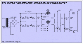
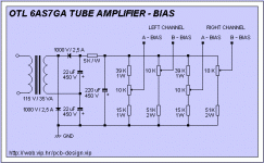
Link for old cathode follower OTL
http://www.audiodesignguide.com/otl/otlse.jpg
This would be low power, but an adjustable bias version od something Joel posted a few pages back. With the available drive, 8 or 10 tubes could be used, or 4 or 5, 6336 🙂
http://www.audiodesignguide.com/otl/otlse.jpg
This would be low power, but an adjustable bias version od something Joel posted a few pages back. With the available drive, 8 or 10 tubes could be used, or 4 or 5, 6336 🙂
KEEP IN MIND...
Hi,
Yes,you smart people...it was also designed for a 16 Ohm load.
You're oh so bright,😀
Hi,
Yes,you smart people...it was also designed for a 16 Ohm load.
You're oh so bright,😀
Hello fdegrove,
I will build it as monoblocks.
Do you maybe know at what bias current this OTL
would work best.
Is there any problem if used 6 or 8 output tubes
per one channel, instead of 4 ?
Regards,
Kristijan Kljucaric
I will build it as monoblocks.
Do you maybe know at what bias current this OTL
would work best.
Is there any problem if used 6 or 8 output tubes
per one channel, instead of 4 ?
Regards,
Kristijan Kljucaric
Re: KEEP IN MIND...
Hey Frank, if you used the 8 or 10 tubes suggested by Scott wouldn't it be able to drive 8 ohms vrs 16 ohms for 4 tubes as suggested by the schema?
dave
fdegrove said:Yes,you smart people...it was also designed for a 16 Ohm load.
You're oh so bright
Hey Frank, if you used the 8 or 10 tubes suggested by Scott wouldn't it be able to drive 8 ohms vrs 16 ohms for 4 tubes as suggested by the schema?
dave
Well, a single 6080 should be capable of a Zo of 142....
Zo=1000000/7000, so if you paralleled 6, you'd get 23 ohms... right? (without NFB)
How's my math?
Zo=1000000/7000, so if you paralleled 6, you'd get 23 ohms... right? (without NFB)
How's my math?
OTL
Hi,
David and Scott,
At the risk of repeating myself:with OTL amps you always face the dilemma of low Zo and power output.
So,yes you could add a few tubes to that circuit,actually 4 of them in a series // configuration + NFB should bring the Zo down to usable levels.
You should discard the zobel network at the output as well since most modern speakers have one build in the x-over or don't need any.
I am not sure that circuit uses 4 // 6080s or 2.
The circuit does not show that clearly.
Keep in mind that the low mu triodes present a rather high input capacitance which is //ed by adding more tubes.
It will require a decent driver stage.
But using the 6336A is not cheap unless you're already sitting on a huge pile of them.
In the long run the 6AS7G/6080 is a better choice.
Other candidates are the EL509/6KG6 and the monster 6C33C.
Cheers,😉
Hi,
David and Scott,
Hey Frank, if you used the 8 or 10 tubes suggested by Scott
At the risk of repeating myself:with OTL amps you always face the dilemma of low Zo and power output.
So,yes you could add a few tubes to that circuit,actually 4 of them in a series // configuration + NFB should bring the Zo down to usable levels.
You should discard the zobel network at the output as well since most modern speakers have one build in the x-over or don't need any.
I am not sure that circuit uses 4 // 6080s or 2.
The circuit does not show that clearly.
Keep in mind that the low mu triodes present a rather high input capacitance which is //ed by adding more tubes.
It will require a decent driver stage.
But using the 6336A is not cheap unless you're already sitting on a huge pile of them.
In the long run the 6AS7G/6080 is a better choice.
Other candidates are the EL509/6KG6 and the monster 6C33C.
Cheers,😉
OTL
Hi,
Fine.
I actually used 8 output tubes per channel on a friends' amp.
It is easy enough to do as long as you keep in mind that your powerxformers needs to be up to it.
Also I //ed the second 6SN7 on each block.
I set bias for 80 mA but it is not critical for sonic results IME.
The best way to avoid problems is to match the output tubes before you stick them in the amp.
Especially discard any tube with widely varying halves.
Cheers,😉
Hi,
I will build it as monoblocks.
Fine.
I actually used 8 output tubes per channel on a friends' amp.
It is easy enough to do as long as you keep in mind that your powerxformers needs to be up to it.
Also I //ed the second 6SN7 on each block.
I set bias for 80 mA but it is not critical for sonic results IME.
The best way to avoid problems is to match the output tubes before you stick them in the amp.
Especially discard any tube with widely varying halves.
Cheers,😉
Re: OTL
I looked through the Hammond catalog, and they have a line of toroidal x-formers that are small and could easily supply an OTL's 1-2 amps of B+. You can start to see why these didn't catch on!🙁
You take out the output tranny, and replace it with 20 lbs of power transformer!😉
fdegrove said:It is easy enough to do as long as you keep in mind that your powerxformers needs to be up to it.
I looked through the Hammond catalog, and they have a line of toroidal x-formers that are small and could easily supply an OTL's 1-2 amps of B+. You can start to see why these didn't catch on!🙁
You take out the output tranny, and replace it with 20 lbs of power transformer!😉
- Status
- Not open for further replies.

