OTL
Hello Mohan,
Good idea.
Before anyone should jump into the deep end may I suggest some informative reading on the subject ?
I keep on noticing that most info on the subject is posted on the web nowadays.
For SE OTL I'd suggest http://www.headwize.com.
For PP OTL http://members.aol.com/aria3/otlpaper/otlhist.htm
http://www.machmat.com/schema/index.htm
There many others,too many to list here.
A google on the subject will turn up the same links I stumbled on.
It wouldn't be a bad idea to implement some of the "recent " ideas on PSU design.If any circuit benefits from a well regulated PSU it must be the OTL.
Greetz,
For another SE otl design (output is taken from the triodes grid!) take a look at Steve Bench's site. Scroll down to the power amp section. There you will find a 2 watt OTL design (no output coupling cap either).
Tom §.
Tom §.
Hi everyone,
Unfortunately by far I do not have enough knowledge to design an OTL by myself but as I`m very interested in building an OTL, I extensively searched the web about this topic since a long time and finally came up with this:
http://www.otlamp.com/articles/ak/index.html
It`s a detailled description of a "Circlotron" output topology, including schematics, part values etc. and to me it looks somehow promising.😎
What do You "tube-heads" thing about it? Any good - or maybe something to change/tweak/add/leave out?
At least it might be a good starting point or a source for helpful information for Your project.
Unfortunately by far I do not have enough knowledge to design an OTL by myself
but as I`m very interested in building an OTL, I extensively searched the web about this topic since a long time and finally came up with this:http://www.otlamp.com/articles/ak/index.html
It`s a detailled description of a "Circlotron" output topology, including schematics, part values etc. and to me it looks somehow promising.😎
What do You "tube-heads" thing about it? Any good - or maybe something to change/tweak/add/leave out?
At least it might be a good starting point or a source for helpful information for Your project.
As the PSU in OTL designs in general have to deliver much higher currents than in equivalent power output transformer designs, I doubt that a regulated power supply will be practicable (at least not for high power amps).🙁It wouldn't be a bad idea to implement some of the "recent " ideas on PSU design.If any circuit benefits from a well regulated PSU it must be the OTL.
OTL
Hello Cocolino,
It wouldn't be a bad idea to implement some of the "recent " ideas on PSU design.If any circuit benefits from a well regulated PSU it must be the OTL.
Sure,it can be done.Look at the Futterman built by NYAL,look at the later Croft designs et all.
I'm convinced it makes the difference between a half decent and an exceptional design.
Nobody ever said it would be cheap nor easy though...
I therefore think it a good idea of Mohan to start out with something relatively simple.
Greetz,
Hello everyone,
Just to let you know that I am working on a few ideas for SE OTL design. Since this is a DIY project, I would like to stick to simple topologies.
For a very simple design, I am thinking of 6C41C tube, Capacitor Coupled to make it idiot proof and safe. I know that there are no good capacitors around but still….
A second design, I am yet to put pencil to paper, uses the concept of holding the grid at a fixed voltage (say –10V) and changing the anode voltage. This is driving the Anode! It may be possible to drive the cathode as well, simultaneously. This is KABE (Kicking At Both Ends…of the output tube). At present this is only a concept that I have. When I get a few spare (continuous hours) I may be able to design one. Does anyone know if such an idea has been thought of before? Are there any flaws in this concept that are apparent? Comments, criticisms, help and suggestions are all welcome.
By the way, and figuratively speaking, the KABE design would call for am amp within an amp. So this topology will almost never be a commercial reality and will remain in the DIY and enthusiast realms.
Mohan
OTL
Hello Mohan,
That's good news.
1/Has anyone ever published the characteristic behaviour of an electrolytic (garden variety) cap into a say 2 to 16 R impedance ?
I mean a big bugger 1000 mF to 5000mF?
No need to tell you I guess,damping factor is even more of an issue here then in a PP OTL design.
2/The second design is kind of an inverted triode mode; anode=grid,grid=anode and on the opposite bank the other way around ?
Never came across a circuit where both anode and grid were driven simultaneously though.
6C41C is also a septar socket tube if memory serves me correctly.
This sounds very interesting if you can get it to work.
Let me know if I can help.
Greetz,
OTL
Mohan,
Think I got you figured out:
"As an infant, Kabe survived a terrible natural disaster on her homeworld only to be captured and sold into slavery..."
Rgds,
🙂 🙂
Mohan,
Think I got you figured out:
"As an infant, Kabe survived a terrible natural disaster on her homeworld only to be captured and sold into slavery..."
Rgds,
🙂 🙂
True OTL Monster!
Hmmmm.....wonder if it would be possible to use something like the RCA 5671 triodes on the output?
With over 3800 watts going to the heaters alone, I think the numbers would be quite impressive, though probably not too practical.
Hmmmm.....wonder if it would be possible to use something like the RCA 5671 triodes on the output?
With over 3800 watts going to the heaters alone, I think the numbers would be quite impressive, though probably not too practical.
Hello everyone,
Just to let you know that I am experimenting with 6C41C tubes. This is my way of getting to know the tube. Any idea where I can get hold of 6C41C-B version?
Mohan
Just to let you know that I am experimenting with 6C41C tubes. This is my way of getting to know the tube. Any idea where I can get hold of 6C41C-B version?
Mohan
Hi
I'm a tubes entusiastic person.
Built OPTs is not a big problem to me.
However I've never built any OPT with 500KHz bandwith. I think anyone was capable of doing it either!
Because of that I've tried hybrid topology. Forgive me the other tube entusiasts! Anyway this seems to play rather well.
Please let me know your opinion about it.
Regards
OTL
Hi,
Are you aware how much your circuit actually resembles that of most OTL PP amps?
Why would you need an OPT with a bandwidth beyond say 100KHz anyway?
And I seriously doubt the hybrid one has such wide bandwidth.
Not that it matters to me anyway.
There are IMO other more important factors than just bandwith to a design,wouldn't you agree?
Nice work BTW.🙂
Regards,
Re: OTL
Yes, is true taht thi circuit is similar to OTL. But I dont know any valve with 4-5 Amps max current. And BJTs are capable of manage that current. The output stage is almost transparence. And has a current super gain (aprox 500000). Due large intput impedance.
SACDs have a large BW (96 Khz). And this is why I'm looking for a large BW tube amp.
Of course, the large BW of my design is obtaind with 14dB of NFB. In open loop I Have only 46 Khz @ -1 dB.
The problem with my other OPTs on tube amps is the phase shift, that not allows a large amount of OANFB.
This was the main reason to try this topology.
May be. it is possible, make an OTL topology with a OPT.
You may think I'm crazy!
But, my theory is, a OPT auto-transfomer have less leakage indutance end less shunt capacitace, due less phase shift.
I've not tried yet!
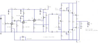
Please see the preliminary schem.
Regards🙄
Yes, is true taht thi circuit is similar to OTL. But I dont know any valve with 4-5 Amps max current. And BJTs are capable of manage that current. The output stage is almost transparence. And has a current super gain (aprox 500000). Due large intput impedance.
SACDs have a large BW (96 Khz). And this is why I'm looking for a large BW tube amp.
Of course, the large BW of my design is obtaind with 14dB of NFB. In open loop I Have only 46 Khz @ -1 dB.
The problem with my other OPTs on tube amps is the phase shift, that not allows a large amount of OANFB.
This was the main reason to try this topology.
May be. it is possible, make an OTL topology with a OPT.
You may think I'm crazy!
But, my theory is, a OPT auto-transfomer have less leakage indutance end less shunt capacitace, due less phase shift.
I've not tried yet!
Please see the preliminary schem.
Regards🙄
OTL
Hello,
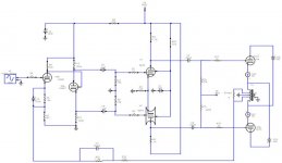
Seems we now have a high speed designer.😉
Looks good to me.
Apparently you already know what tubes can deliver high amounts of current.
Having low output impendance at the outputstage allows for better bandwidth of the OPT and makes it easier to design so we have a win-win situation.
Although I can not come up with any big brandnames right now I suppose some product like this must already be on the market.
Shouldn't stop you from trying though.
It makes me wonder which of the two designs would be preferred on listening tests.
Interesting.
Cheers,
Hello,
Seems we now have a high speed designer.😉
Looks good to me.
Apparently you already know what tubes can deliver high amounts of current.
Having low output impendance at the outputstage allows for better bandwidth of the OPT and makes it easier to design so we have a win-win situation.
Although I can not come up with any big brandnames right now I suppose some product like this must already be on the market.
Shouldn't stop you from trying though.
It makes me wonder which of the two designs would be preferred on listening tests.
Interesting.
Cheers,
OTL
Mohan,
In case you're still looking for sources on the 6C41:
http://www.diyaudio.com/forums/showthread.php?s=&threadid=6849
Maybe helpful?😉
Cheers,
Mohan,
In case you're still looking for sources on the 6C41:
http://www.diyaudio.com/forums/showthread.php?s=&threadid=6849
Maybe helpful?😉
Cheers,
Hello everyone,
Last week end, I have completed the prototype of a Parallel Single Ended amp using three 6C41C tubes. This amplifier is output transformer coupled and is intended as the forerunner to my proposed OTL on this forum.
On Thursday, 12th December, we had our monthly Club meeting at my factory. The amp was played on Alfredo Horn using Lowther PM7C. I have not heard such authority and total control of the speaker by any SE amp to date. Dynamics were terrifying and I had to request the members to turn down the volume for fear of damaging the expensive Lowther drivers. Geoffrey, one of our very experienced members said “I have never heard any thing like this that parts my hair”. Music played included Doug Macleod, Cantate Domino, Carmina Burana, Terry Evans and so on… The meeting closed at 0245hrs the next morning.
Compared to my dedicated Lowther amp (1.5Wrms/channel), the 6C41C amp had more authority, dynamics but slight loss of finer detail. Both amps sound very ‘OPEN’ like a concert in open air. Mind you, this amp had only 5 hours of operation (test bench included) prior to the Club meeting.
This amp will be a commercial offering from me. The next project, OTL, will be developed for this forum as promised.
On the test bench, the 6C41C amp delivers 15Wrms into an 8 ohm load at less than 2% THD. This was measured at 40Hz, 50Hz, 100Hz, 200Hz, 500Hz, 1kHz, 2kHz, 5kHz, 10kHz, 20kHz, 30kHz, 40kHz, 60kHz, and 80kHz. The –1.5dB levels are at 20Hz and 100kHz.
Pulse rise time for square wave 1kHz is 4ms.
Power supply ripple is 8mVpk
Signal to noise ratio for full power output is 65dB.
Channel Separation is also around 65dB.
Output impedance of the amp is 1ohm.
There are some hot issues that I need to attend to! All components (both channels) are mounted on a rather large 3mm thick aluminium plate. This gets to almost 900C after 60 minutes into operation. Ceramic sockets for the output tubes conduct heat and so do the cathode bias resistors. Approximately 300W is dissipated to the miserable chassis. I need to use spacers and a separate mounting plates for the sockets. Heat sinks are a must for the cathode resistors.
All in all a worthwhile effort.
Any new ideas on SE OTL for the forum? I need ideas and do not be afraid to put it out on this forum even though you are in doubt. If the ideas are worthwhile we will look into it and together, we can make them work. Let us make this a creative forum.
Mohan
HOWDY MOHAN
Hi,
Glad to see it was such a big success!
I'm sure Bas will be pleased too since he uses the same output tube.
Sure whish all the commercial success you deserve.
re:OTL SE,I always had good results from an SRPP stage a la Philips.
OTL in general,there is not much one can improve other than the PSU regulation.
Let us know what you have in mind though.
Ciao,
- Status
- Not open for further replies.