Maybe we are straying of of topic...
As far as i know, Philips never made otl amplifiers with more than 2 EL86's per channel, but Valvo (a German company, but part of the Philips concern) published a schematic of an otl amplifier with 2 E130L's per channel wich produces 25 Watt into 400 Ohm.
Philips made many different types of 800 (and 400) Ohm loudspeakers. They were mostly full-range loudspeakers, often with whizzer cones. Philips made only one woofer for 800 Ohm, the AD5201A (nicknamed "Bombardon") wich is rated for 20 Watt. The conus is made of polystyrene and is attached tot the rim in a rather unique manner. In the AD5055 loudspeaker enclosure it was combined with 2 x AE37011 (400 Ohm) in serie for mid/high.
I think 20 Watt is the highest power rating for Philips 800 Ohm loudspeakers, but most of them have high sensitivity.
I use the AD5201A "Bombardon" in combination with the 9710AM. See:
OTL800: OTL Versterkers met zeer veel tegenkoppeling
and
OTL800: Gesloten Basboxen met Philips AD5201A Bombardon
and
OTL800: Bombardon - Een bijzondere 20-Watt Lagetonenluidspreker
Greetings,
Robert
Last edited:
Well, four EL86's in one device 😀!
Yes, I'm afraid that's not what you mean. I think that a design like this may easily be upscaled just by paralleling more tubes, though. At some certain time you might need to re-think the driver stage that it copes with the increased input capacitance of the power tubes.
Best regards!
Yes, I'm afraid that's not what you mean. I think that a design like this may easily be upscaled just by paralleling more tubes, though. At some certain time you might need to re-think the driver stage that it copes with the increased input capacitance of the power tubes.
Best regards!
I think this has strayed off topic, but very interesting nonetheless!
I have a mint AG9014 and can't make up my mind whether to sacrifice a console radio to scavenge a couple of 800ohm speakers, or adapt it so that it can work with 8 ohm speakers (and thank you for that schema suggestion, Mona!).
Even the speaker plugs are unobtainable.
I am nowhere near proficient enough at this hobby to tackle updating that amp yet, so it is safe for now ;-)
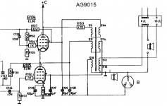
The 800 ohm system was a Philips proprietary thing; I heard that Audax in France manufactured some 800 ohm speakers but I never saw them. AG9014 , AG9015 and AG9018 stereo Hi-Fi amplifiers had 4 EL86 tubes. They were usually paired with the AD5046 or AD5055 speaker box. I believe that the biggest 800 drivers are 9760 and 9762 (12 inches).
This design was also published on several DIY magazines because it was cheaper than conventional amplifiers due to the lack of output transformers. In Italy it was published on "Quattrocose illustrate", June 1967 ; in Sweden on "Radio & Television", April 1964.
This design was also published on several DIY magazines because it was cheaper than conventional amplifiers due to the lack of output transformers. In Italy it was published on "Quattrocose illustrate", June 1967 ; in Sweden on "Radio & Television", April 1964.
There are quit a few 800 Ohm loudspeakers circulating in (mostly) The Netherlands. You could post a request for some on Dutch forums (like: Nederlands Forum over Oude Radio's, see Nederlands Forum over Oude Radio's.
I am not sure if the schematic Mona proposed is actually gonna work. An 800 to 8 ohm transformer after the output capacitors looks safer to me.
Greetings,
Robert
I am not sure if the schematic Mona proposed is actually gonna work. An 800 to 8 ohm transformer after the output capacitors looks safer to me.
Greetings,
Robert
You'e referring to the schematics in #37? I strongly think a power transformer that was made according to nowaday's standards will be surperior in terms of insulation, hence safe enough 😉.
The schematics still has to be tried. Sadly I've found that toroidal power transformers with dual (115 + 115 Vac) primaries are somewhat hard to find here in Germanistan.
Best regards!
The schematics still has to be tried. Sadly I've found that toroidal power transformers with dual (115 + 115 Vac) primaries are somewhat hard to find here in Germanistan.
Best regards!
Hi Kay,
With 'safer' i meant that my proposal will surely function, not that the proposal of Mona would be unsafe in terms of health.
Amplimo (Netherlands) has lots of toroidal transformers with 2 x 115 V primaries. See:
Toroidal Transformer Amplimo - toroidal-transformer.com
Plitron in the UK also sells them.
Greetings,
Robert
Philips did the same thing in the AG9015.The UPT has several windings, probably for better coupling.I am not sure if the schematic Mona proposed is actually gonna work. An 800 to 8 ohm transformer after the output capacitors looks safer to me.
And for those who want more power for 400/800Ω speakers there was the AG9007, 60W in 400Ω !
Mona
Attachments
Hi Mona,
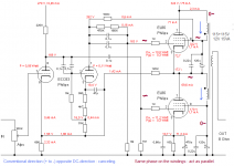
In your proposal winding S10 is ommited, wich leaves the double choke to do the coupling tot the secondary. But if i understand the circuit correctly, the audio signals in the two chokes will cancel each other out. That makes me wonder if your proposal will function correctly.
Greetings,
Robert
In your proposal winding S10 is ommited, wich leaves the double choke to do the coupling tot the secondary. But if i understand the circuit correctly, the audio signals in the two chokes will cancel each other out. That makes me wonder if your proposal will function correctly.
Greetings,
Robert
Hi Robert,
do they really? In Mona's design the transformer windings are wired out of phase. Same with the output voltage wrt to gnd and Vb.
If this weren't so, the Phlips AG 9015 design also wouldn't work.
Best regards!
do they really? In Mona's design the transformer windings are wired out of phase. Same with the output voltage wrt to gnd and Vb.
If this weren't so, the Phlips AG 9015 design also wouldn't work.
Best regards!
Btw, I wonder if fixed bias also would be possible with that Philips OTLs. Biasing the upper tube would be somewhat complicated or tricky, I think, but might be feasible using nowaday's technologies (opamp based integrators).
Best regards!
Best regards!
If the control grid of the upper tube is fixed (~half way) or adjusted with a feedback loop, then you only have to adjust the bias of the lower one, the other will follow automaticaly.Btw, I wonder if fixed bias also would be possible with that Philips OTLs. Biasing the upper tube would be somewhat complicated or tricky,
Mona
Indeed (I did put start of winding dots), the two primary windings are parallel.Foor AC it is an 115V to 12V tranformer. 115/12 = ~10 gives with 8Ω on the 12V 8x10x10 = 800Ω on 115V.Hi Robert,
do they really? In Mona's design the transformer windings are wired out of phase. Same with the output voltage wrt to gnd and Vb.
If this weren't so, the Phlips AG 9015 design also wouldn't work.
Mona
In the original design (see post 33) the double choke is connected so that the two dc currents cancel each other out. By doing so, the double choke has the inductance (2 x 60 H) it needs at a relative small size (as no airgap in the core is needed). I assume that also the ac currents are cancelled out (but i am not sure about this). If you connect them the other way, they would not cancel out. But is this not a problem in view of the required inductance of the chokes? And does the (full) power of the amplifier transfers correctly through the choke windings?
The upper EL86 is not cathode biased. The coupling capacitor to the upper EL86 is bypassed by a resistor of 620K. So it's more or less fixed bias allready (but with signal is swinging up and down by the bootstrapped connection to grid 2 of the upper EL86).
Greetings,
Robert
The upper EL86 is not cathode biased. The coupling capacitor to the upper EL86 is bypassed by a resistor of 620K. So it's more or less fixed bias allready (but with signal is swinging up and down by the bootstrapped connection to grid 2 of the upper EL86).
Greetings,
Robert
Yes, DC cancels out but for AC it's in phase.If it was not the choke would be a short circuit for AC, become useless.And 2x60H parallel on the same core is still 60H, in series and in phase it becomes 240H, out of phase nullH (short cicuit)Assuming 100% coupling !In the original design (see post 33) the double choke is connected so that the two dc currents cancel each other out. By doing so, the double choke has the inductance (2 x 60 H) it needs at a relative small size (as no airgap in the core is needed). I assume that also the ac currents are cancelled out (but i am not sure about this).
The drive for the upper tube is related to it's cathode as it is for the lower.The upper EL86 is not cathode biased. The coupling capacitor to the upper EL86 is bypassed by a resistor of 620K. So it's more or less fixed bias allready (but with signal is swinging up and down by the bootstrapped connection to grid 2 of the upper EL86).
The voltage divider sets the control grid to get ± half the supply voltage between the tubes.Since the two are in series the upper one gets the same bias current as the lower, set by it's cathode resistor.
Mona
Attachments
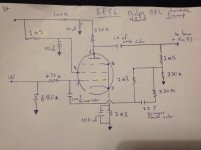
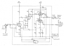
Have started tracing the circuit out.
wondering if the circuit that comes off pin 9 ef86 phono preamp is some sort of negative feedback?
Theres a couple of values im not sure of on two of the ceramic tube capacitors. the small peach colored one says 22 and the other is a green one 100? they are both smaller in physical size than the white 10nf though maybe low voltage rated. not quite sure,
hoping some one might be familiar with this arrangement and know if they are pf or nf, instead of de-soldering to measure. also wondering if the tube ceramics are reliable like the ceramic disc shaped ones?
Attachments

This design was also published on several DIY magazines because it was cheaper than conventional amplifiers due to the lack of output transformers. In Italy it was published on "Quattrocose illustrate", June 1967 ; in Sweden on "Radio & Television", April 1964.
Here is the Swedish magazine ...
"Radio & Television", April 1964
The amplifier is described from pg 58.
Is there any reason why I could not build this with a small toroid (115 + 115 primary, 25 secondary, 50VA) and use 8ohm speakers?
I have 4 x PCL200, and the pentode part has a similar Ra to the EL86, and the triode has a mu around 55, whereas the original ECC83 is 100. Power would be less, and values would need to be tweaked, but any reason why that would be bad substitute?
Here is the schema.
This magazine is quite famous here in Sweden since it is meant to have been the most stolen magazine ever from libraries, and there are still a few self builds popping up for sale from time to time.
Another great example of this thinking are the Stig Carlsson's OA6 type 1 speakers, with two inbuilt OTL amplifiers per speaker cabinet.
Sonab OA-6 Type 1
Attachments
Hi Paul,
Yes, it's negative feedback, but frequency dependent. It's there to correct the frequency response as recorded on discs and possibly also to correct the frequency response of the pick-up element. The values of the tubular capacitors values are in pf. On Dutch radio forums they are regarded as reliable.
Greetings,
Robert
Here is the Italian magazine, Quattrocose Illustrate, June 1967 http://www.introni.it/pdf/Quattrocose 1967_04.pdf . It has been recently published again with modernizations (mostly on the power supply) on "Costruire Hi-Fi", issue 230 - June 2018.
Thanks to OldHector for the informations about the Stig Carlsson Sonab OA6 speaker. I didn't knew that the first version had a 800 ohm OTL amplifier inside, similar to the Coalscuttle. To use your AG9014 with standard speakers, the Hammond 119DA audio transformer is a good option. Don't buy a 800 ohm speaker meant for tabletop radios. The Philips "master" series speakers are the only one with real Hi-Fi qualities.
There is no need to change tubular capacitors.
- Status
- Not open for further replies.
- Home
- Amplifiers
- Tubes / Valves
- OTL turntable EL86 speaker wiring