hi all,
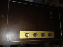
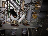
am working on an old mono philips hi-z stand alone turntable in working order, ez80, ef86/ ecc83, and two el86. I think pp or similar arrangement, not single ended.
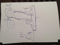
I'm wanting to wire in a 10" speaker into the wiring with out doing damage to the amp and keep the two existing 6" in use but are not sure how to wire. am not sure best way to wire this type of amp with the static discharge on the baskets. any diagrams would be great thanks
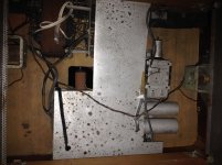
also im getting a very poor reading when i do earth continuity safety measure test. i get an ohm or so from earth plug pin to where its grounded to the foot on the PT mounted to wood ........ but a very very dangerously poor reading to amp chassis and shielding panels. does anyone know if these type of old turntables use a ground lift? before i make a good connection from chassis to earth, thanks
ps i left out the other wiring etc between the el86's on drawing because it was quit strange and heater appeared to connect to anode... but what ever the design it works well.
am working on an old mono philips hi-z stand alone turntable in working order, ez80, ef86/ ecc83, and two el86. I think pp or similar arrangement, not single ended.
I'm wanting to wire in a 10" speaker into the wiring with out doing damage to the amp and keep the two existing 6" in use but are not sure how to wire. am not sure best way to wire this type of amp with the static discharge on the baskets. any diagrams would be great thanks
also im getting a very poor reading when i do earth continuity safety measure test. i get an ohm or so from earth plug pin to where its grounded to the foot on the PT mounted to wood ........ but a very very dangerously poor reading to amp chassis and shielding panels. does anyone know if these type of old turntables use a ground lift? before i make a good connection from chassis to earth, thanks
ps i left out the other wiring etc between the el86's on drawing because it was quit strange and heater appeared to connect to anode...
but what ever the design it works well.Attachments
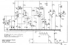
According to your partial schematic, this device appears to use Philips' "low-end 800 ohms" scheme, with a full 40 mA anode current through the speaker. I am attaching a diagram of a Philips radio that you can compare with yours. This cost-cutting measure was often paired with hot-chassis, be sure to check this out and add an insulation transformer. If your turntable works, look at the cone at power up: if you see an outward shift when the high voltage power supply is present, you have this type of amplifier. To facilitate heat dissipation, a resistor was sometimes added in parallel to the loudspeaker or several loudspeakers were used. Constant heat dissipation will cause long-term damage to the speaker. I would not use your rare 9758A driver on this application.
Attachments
got it pretty worked out now, will run the two 400 ohm in parallel as 200 ohm and then in series with the 10" 700ohm for total 900 ohms which is pretty close to the 800 ohms the amp was seeing before.
do you reckon if it is a hot chassis i would get a voltage reading from chassis to earth? do you think the configuration i came up with would be bad?
what if i just ran the 10" with out the two 6"... even though the " is mid range driver I think?
do you reckon if it is a hot chassis i would get a voltage reading from chassis to earth? do you think the configuration i came up with would be bad?
what if i just ran the 10" with out the two 6"... even though the " is mid range driver I think?
Will have a look tomorow, i think it might be similar to this schematicAccording to your partial schematic, <snip>
Attachments
You should check first if you have constant DC current trough the speakers. If this is the case, measure or calculate the power dissipation in the 10'' speaker voice coil to be sure not to damage it. To measure it, I would use a temporary 700 ohm power resistor in place of the 10'' speaker. If there is no DC current flowing, the series/parallel arrangement you devised may be ok. If there is DC current, then stop and rethink your plan.
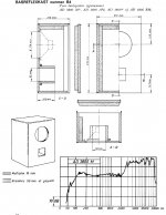
According to Philips data book, the 9758 belongs to the top-of-the-line "master" range, it does have a resonant frequency of 50 Hz with 10W power handling capability, while the AD3800M is a far cheaper Class 3 (maximum sensitivity) "universal" range speaker with 75 Hz resonant frequency and 6w power handling capability. I attach the original Philips bass reflex suggested design for the 3800M. According to my Philips 1960 product catalog, full data of the "master" range speakers are on the EP 7521 datasheet, but I don't have it.
According to Philips data book, the 9758 belongs to the top-of-the-line "master" range, it does have a resonant frequency of 50 Hz with 10W power handling capability, while the AD3800M is a far cheaper Class 3 (maximum sensitivity) "universal" range speaker with 75 Hz resonant frequency and 6w power handling capability. I attach the original Philips bass reflex suggested design for the 3800M. According to my Philips 1960 product catalog, full data of the "master" range speakers are on the EP 7521 datasheet, but I don't have it.
Attachments
thats awsome thanks, i will check for dc current tomorrow,
i havent re-capped yet and i can hear them swirling and hissing so i know they are out of wack.
wondering if the caps could be responsible for the dc current through the speakers? there is 26k impedance between the chassis and ground. theres no stray voltage going from chassis to earth. hoping not to have to trace the schematic
Hi, I checked for dc current and got about 9.3 mA once then around 3 mA mostly traveling through the standard two speakers. I'm not sure if this gives any clues, the speakers did sit out slightly when powered up when warm.You should check first if you have constant DC current trough the speakers. If this is the case, measure or calculate the power dissipation in the 10'' speaker voice coil to be sure not to damage it. To measure it, I would use a temporary 700 ohm power resistor in place of the 10'' speaker. If there is no DC current flowing, the series/parallel arrangement you devised may be ok. If there is DC current, then stop and rethink your plan. .
i havent re-capped yet and i can hear them swirling and hissing so i know they are out of wack.
wondering if the caps could be responsible for the dc current through the speakers? there is 26k impedance between the chassis and ground. theres no stray voltage going from chassis to earth. hoping not to have to trace the schematic
There are several implementations of that Philips SEPP OTL design with EL86's (the original tubes were UL84's, btw). All but the more sophisticated ones with additional chokes couple the high Z speaker in the same way as your's, just to safe components that feed the upper valve's screen. As there were no other purposes for high Z speakers than these OTL concepts, we can safely assume that they cope with (small) DC currents.
Best regards!
Best regards!
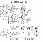
3mA reminds me of the audio output stage of the Philips 21TD144A TV. It is meant to cut costs, but it has a clever circuit to reduce the current through the speakers. Be aware that you may have high voltage on the speaker wires. 3 mA will cause less than 1 W of power dissipation on the speaker coil. It is not harmful, but the speaker coil will act as a fuse and will blow in many fault conditions. This is one of the reasons why 400 and 800 ohm speakers have been labeled as "weak" and not very reliable. Your fullrange speaker has value, it's up to you to decide if it's worth the risk to use on this application.
With DC passing through the voice-coil, the cone will be slightly offset from it's rest position which may cause some 2H distortion. If the amplifier has any 2H distortion, you might find that the speaker sounds rather different according to the polarity of the connections.
This schematic is the standard that Philips used for the 400 to 800 Ohm speakers. The speakers are DC free! In the attached schematic this is due to capacitor C50. If you have any leakage through the speaker this simply means the cap is seriously leaking. Before going on please replace this old electrolytic - it will safe your speakers (the 400 Ohm speakers where not build to accept any DC current) and it will be good for your own safety!Will have a look tomorow, i think it might be similar to this schematic
The circuit of post3 is not what Paul amp has.This schematic is the standard that Philips used for the 400 to 800 Ohm speakers. The speakers are DC free! In the attached schematic this is due to capacitor C50. If you have any leakage through the speaker this simply means the cap is seriously leaking. Before going on please replace this old electrolytic - it will safe your speakers (the 400 Ohm speakers where not build to accept any DC current) and it will be good for your own safety!
If you look at his sketch the resistor R43 of post3 is replaced by the speakers.Like that the screen current goes through the speakers.
With the speakers inside the same box as the amp that's ok but with an extra one outside
The speaker is at V+ level Mona
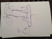
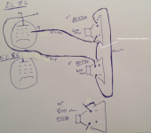
The real circuit must be different from the hand-drawn sketch.
A speaker between B+ and the screen grid does not make any sense. What is the purpose of the other EL86? Where is the AC signal coming from to make the amp reproducing sound?
The EL86 was invented to be able to build a totem-pole output stage with the limited available B+.
Engineers at that time had the goal to get max power as cheap as possible - hence the 400 or 800 Ohm speakers to save the output transformer. See the original EL86 datasheet from Philips!
Of course it does! There's a 'lytic between cathode and screen, and there's the speaker between plate/+Ub and screen. Hence both components play a double role each: Screen decoupling and output coupling for the cap, screen feeding and output load for the speaker.A speaker between B+ and the screen grid does not make any sense. What is the purpose of the other EL86?
Best regards!
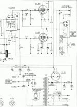
I attach the schematic of the audio output stage from a Philips TV set of the time. This circuit was widely used by Philips back then. The potentiometer marked L is the volume control.
By the way: PL84 is the 300mA filament version of EL86.
By the way: PL84 is the 300mA filament version of EL86.
Attachments
Last edited:
Well, it's a Philips device from the late '50. They were making a point to be different from the others, you expect to see bold decisions. And they were a tube manufacturer. They needed to fit as many tubes as possible inside the product. This TV set has two small rectifier tubes, replacing the standard one everyone else was using. The audio output stage was usually built with a single triode/pentode such as PCL82. We have 3 tubes here. On the positive side, output transformer was usually low quality back then, and by removing it, the audio quality became better than average.
Last edited:
- Status
- This old topic is closed. If you want to reopen this topic, contact a moderator using the "Report Post" button.
- Home
- Amplifiers
- Tubes / Valves
- OTL turntable EL86 speaker wiring