Chris do you recall the spec or part # for the thermistor and could you clarify the location of it for me. Did you put it in series of the hot line; on the primary side of the transformers?
Also I am having trouble finding a few parts:
R8 & R9, the 4.7M ohm 3500 volt metal film
R10 & R11, the 1M ohm 1% 2W 500 volt metal film
If anyone can drum up Mouser part numbers that would be the best as the rest of my parts I have sourced from Mouser.
Also I am having trouble finding a few parts:
R8 & R9, the 4.7M ohm 3500 volt metal film
R10 & R11, the 1M ohm 1% 2W 500 volt metal film
If anyone can drum up Mouser part numbers that would be the best as the rest of my parts I have sourced from Mouser.
Chris do you recall the spec or part # for the thermistor and could you clarify the location of it for me. Did you put it in series of the hot line; on the primary side of the transformers?
There is a current inrush limiter that you can get from Digikey called a CL-30 that should suit the bill, pn# KC003L-ND
You want the hot side of the line to go through the CL-30 to the fuse and from there to the power switch. That way the power switch is protected from inrush and you are protected if the fuse shorts to the chassis.
No-one has mentioned grounding so far, so I think it might be worth talking about: do not tie any of the amplifier circuit to chassis ground. Instead, it should all go to a central ground in the amp. Then what you do is tie the chassis to the center pin if the IEC or ground wire of your power cord. Then just put a 10 to 100 ohm resistor between the amp circuit ground and the chassis, and you will have no worries. This way you have have the amp grounded into the wall and not have any buzz problems with ground loops if your preamp is also grounded.
Excellent grounding points. Thanks! Especially important in Circlotron amps, I'd imagine.
Stuart
Excellent grounding points. Thanks! Especially important in Circlotron amps, I'd imagine.
Stuart
Maybe so. I'm not sure that Circlotrons have anything to do with it, but if you follow this grounding technique, the amp will be very quiet, even on horns.
Now I'm not used to doing a lot of processing to the DC power supplies for the output section of an OTL, on account of the amp might need a substantial amount of current on transient peaks. I have preferred the brute force method of very large filter caps fed by robust rectifier bridges. As a result there is a small sawtooth waveform on the power supply rails, but if the amp is balanced properly, you won't hear it even on very sensitive speakers.
There is a current inrush limiter that you can get from Digikey called a CL-30 that should suit the bill, pn# KC003L-ND
You want the hot side of the line to go through the CL-30 to the fuse and from there to the power switch. That way the power switch is protected from inrush and you are protected if the fuse shorts to the chassis.
No-one has mentioned grounding so far, so I think it might be worth talking about: do not tie any of the amplifier circuit to chassis ground. Instead, it should all go to a central ground in the amp. Then what you do is tie the chassis to the center pin if the IEC or ground wire of your power cord. Then just put a 10 to 100 ohm resistor between the amp circuit ground and the chassis, and you will have no worries. This way you have have the amp grounded into the wall and not have any buzz problems with ground loops if your preamp is also grounded.
That's the first I've seen of the current limiting resistor. That looks like it would have applications in any amplifier with a large power transformer.
Do you know how many volts drop across the current limiter? I read the resistance as 2.5 ohms at 25C on the datasheet, but I don't know how hot it gets either. The resistance in operation is obviously much less.
Chris do you recall the spec or part # for the thermistor and could you clarify the location of it for me. Did you put it in series of the hot line; on the primary side of the transformers?
Also I am having trouble finding a few parts:
R8 & R9, the 4.7M ohm 3500 volt metal film
R10 & R11, the 1M ohm 1% 2W 500 volt metal film
If anyone can drum up Mouser part numbers that would be the best as the rest of my parts I have sourced from Mouser.
I am using CL-40, very like the one Atmasphere mentioned. Its Mouser part number is 527-CL40. Indeed, I put it in the hot line on the input to the transformers. It helps because otherwise with toroids, the current when you switch on can be pretty high.
I'm not sure why Tim Mellow specifies 3.5kV for R8 and R9; I ignored that. Clearly there are no voltages of that magnitude in the amplifier, so there would seem to be no essential reason for sticking to his specification there. Maybe there is an issue of the quality of the resistors, but nothing disastrous will happen if you just get normal ones.
Likewise, I didn't get anything special for R10 and R11. Even if they had 500V across them, they would be dissipating only 0.25W. Maybe I'm being too naive, but I would assume any 0.5W resistor of 1 Mohm resistance must, by definition, be perfectly OK with 500V across it.
Chris
Last edited:
That's the first I've seen of the current limiting resistor. That looks like it would have applications in any amplifier with a large power transformer.
Do you know how many volts drop across the current limiter? I read the resistance as 2.5 ohms at 25C on the datasheet, but I don't know how hot it gets either. The resistance in operation is obviously much less.
The CL-30 runs about 60 milliohms after it warms up. The idea is simply to prevent damge to your switch contacts when you turn the amp on. Its a good idea for almost any amplifier to have something like this.
The CL-30 runs about 60 milliohms after it warms up. The idea is simply to prevent damge to your switch contacts when you turn the amp on. Its a good idea for almost any amplifier to have something like this.
That's what I'm thinking - this looks like it would be good for almost any amp with a big power tranny. I get a big "thump" if I happen to flip the power switch at the wrong part of the 120VAC waveform coming in on the mains. I suspect it's not good for the switch, the power transformers, and any other eqipment that's on the same circuit (switching on flickers the lights sometimes with a voltage dip).
Thanks for the info. I'll try them.
I have another application - for SMPS powered heaters. I use SMPS (switched mode power supply) on some of my heaters. For some directly heated cathode tubes sometimes the SMPS takes multiple "attempts" to start. Sometimes this takes 30 seconds or more on a new amp I'm working on (GM70). It's the inrush curent on the cool filament that's causing the problem. My solution was going to be a resistor in series with the heater so the SMPS can start, then use a switch to bypass the resistor once the filament heats up some and increases its resistance.
This resistor is a MUCH easier and more convenient solution. I was even considering chokes, but these are about 1000 times smaller and about 10-20 times less expensive. Thanls again for the info.
sampleaccurate,
Another advantage of the limiters is reduced load on SS diodes. When used with big cap banks, inrush currents can be tremendous. I switched from Hexfreds to Schottky diodes only to find out the Schottky diodes had no sense of humor when it came to exceeding the maximum rated current. In operation, no problem, but cold charging that cap bank made them go boom and let out lots of magic smoke. Limiters fixed that.
About the SMPS for heaters. Um, you may want to rethink that. They do tend to be noisy and heaters transmit a lot of noise on their supplies to the cathode, where they are amplified. Just my

Stuart
sampleaccurate,
Another advantage of the limiters is reduced load on SS diodes. When used with big cap banks, inrush currents can be tremendous. I switched from Hexfreds to Schottky diodes only to find out the Schottky diodes had no sense of humor when it came to exceeding the maximum rated current. In operation, no problem, but cold charging that cap bank made them go boom and let out lots of magic smoke. Limiters fixed that.
About the SMPS for heaters. Um, you may want to rethink that. They do tend to be noisy and heaters transmit a lot of noise on their supplies to the cathode, where they are amplified. Just my
Stuart
Stuart,
First, thanks for the info! This is a big help to me.
I've concluded that the SMPS debate will never end. All I can say is that I've used them on both a KT88 PP amp (the "Oddwatt" SIPP amp designed by Bruce Heran) as well as a 300B amp with directly heated cathodes. The noise that I've been warned about simply can't be found with my scope. It's just not there. I put a 100uf electrolytic and a 1uf tantalum across the outputs of the SMPS and when I measure the noise on the filament supply it's below my ability to measure or hear. I'm in the middle of a discussion on another forum that pertains to this application.
Right now I'm also starting to build a 6C33C OTL amp that will require power for eight heaters, each of which needs over 3 amps at 12 volts. The use of SMPSs drastically reduces the size, weight, and cost of the PS for the heaters. All I can say in my defence is that I've used the SMPS now on both a DHT (300B) as well as an indirectly heated KT88 amp and I've had no issues!
Thanks for the advice and input. It's much appreciated. One day I intend to do some serious comparison testing of AC vs DC on a power triode with a directly heated cathode. If indeed AC or DC created from a transformer using a diode rectifier and a regulator is sonically superior to DC from an SMPS I'll change my future designs. I'm not trying to defend the SMPS, just trying to gain knowledge.
Thanks again.
Stephen
Also I am having trouble finding a few parts:
R8 & R9, the 4.7M ohm 3500 volt metal film
R10 & R11, the 1M ohm 1% 2W 500 volt metal film
.
Since the whole Amp is DC coupled special atention must be paid for quality of this four resistor(R8 & R9,and R10 &R11).they are placed in very critical Amps points.
R8 & R9(4,7M/3,5KV)quality is important beacose standard quality of 4,7M resistor want to change the own value, often raising up the resistance over the time, and that well be resulting in Bad Amp DC stability.
You can replace this 4,7 M/3,5KV (R 8 & 9 )with five 0,25W/1% resistors conected in series(1M+1M+1M+1M+680K=4,68M)
Best Regards 🙂
That's an interesting observation. I too could not figure out why the resistors were specified the way thet are.
Thanks!
Anyone finished with this amp yet? I'm curious how the large resistance drives the capacitance of the driver tubes and how it behaves with the nfb loop.
Anyone finished with this amp yet? I'm curious how the large resistance drives the capacitance of the driver tubes and how it behaves with the nfb loop.
I'm well underway but I just found out the place I purchased the tubes from (in Russia) took 19 days to ship (I ordered 19 days ago and they shipped today - talk about slow service), which puts me back a couple of weeks. All parts except the tubes will be in this week.
I bought 4 1M and 1 700K (689K I think) 1% resistors for the 4.7M. I'll juggle them around to get the match within less than 1% for the 4.7M required.
I was also a little curious about the apparently large output resistance of the preamp section being able to handle the capacitive load of the drivers, but the Miller capacitance of pentodes is small compared to triodes as I understand it, and the amp has already been constructed by others and it does work.
The cap across the 4.7M acts as a short for AC, so you're really directly connecting the output of the preamp stage to the driver stage. You have the added load of a 1M to ground (actually to -430 volts but it's still a signal ground). I don't see a problem there.
Last edited:
Anyone finished with this amp yet? I'm curious how the large resistance drives the capacitance of the driver tubes and how it behaves with the nfb loop.
I'm getting a more or less flat response from about 3Hz up to about 100KHz with mine; as sampleaccurate says, the capacitors bypassing the 4.7MOhm resistors make sure the AC gets through.
I had to add a tiny amount of capacitance in parallel with the the feedback resistor R3, to suppress a bit of ringing on a high frequency square wave. All it took was two 1-inch long insulated single-core bits of wire twisted together; probably about 1pF or so.
Chris
I'm getting a more or less flat response from about 3Hz up to about 100KHz with mine; as sampleaccurate says, the capacitors bypassing the 4.7MOhm resistors make sure the AC gets through.
Chris
Ah, I see...the schem I have has no caps bypassing those resistors.
(This is a cool design, but I'd use more powerful tubes in the preamp and much lower resistance values. Of course power dissipation goes up, but it's not like this is a cool running amp...)
So this is actually an AC coupled amp after all....MOHAHAHAHAHA!!!
I discovered almost by chance that the ringing effect I was mentioning was affected when I applied the probes of a dvm while I was taking measurements, and that led me to discover that I could eliminate it with the mini twisted-wire (adjustable!) capacitor.
By the way, Tim Mellow says in the article that one can omit the coupling capacitors between the first and second stages, thereby reducing the feedback from 26dB to 11dB. It would come at the cost of a considerable increase in output impedance, aside from anything else. But it would give essentially pure DC coupling.
Chris
Chris do you think this ringing has anything to do with the bright sound of the design? I have been listening nw for weeks on and off and the amp is bright in comparison to other OTL's I have and have heard. Love to hear your thoughts.
Thx
D
Well still listening to this amp but for me she so far has not reached a level of sound that makes me say wow really nice. I am thinking of changing the front end out to at 12AT7 which is a direct drop in but lower gain and see what that does. In general I prefer the 12AT7 of the 12AX7. Then I may go with a 6SL7. For sure at this point I will not be building the 4 output tube version of this amp at all.
I just completed another OTL design from AudioXpress which I have posted at this thread:
http://www.diyaudio.com/forums/tube...esigned-glen-orr-audioxpress.html#post2384792
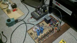
Stop by and give it a look. Right off the bat the design at the new thread is more pleasing to my ears then the Tim Mellow OTL. Here is a pic of my test rig of the amp in the new thread. Not trying to hi-jack this thread in any way I just thought others might be interested.
Thx
D
I just completed another OTL design from AudioXpress which I have posted at this thread:
http://www.diyaudio.com/forums/tube...esigned-glen-orr-audioxpress.html#post2384792
Stop by and give it a look. Right off the bat the design at the new thread is more pleasing to my ears then the Tim Mellow OTL. Here is a pic of my test rig of the amp in the new thread. Not trying to hi-jack this thread in any way I just thought others might be interested.
Thx
D
Attachments
- Home
- Amplifiers
- Tubes / Valves
- OTL designed by Tim Mellow with 4 6C33C?