I have exchanged with a my friend some parts with a 1500VA transformer for OTL and 8 x RIFA 3300uF 200V capacitors.
The my old experience is described in this webpage:
Andrea Ciuffoli - Home Page
It is too simple create a new VARIATION ON THE FUTTERMAN so I would like to get new ideas about this project.
The my old experience is described in this webpage:
Andrea Ciuffoli - Home Page
It is too simple create a new VARIATION ON THE FUTTERMAN so I would like to get new ideas about this project.
Last edited:
This is the transformer specifications, flux 20% less than normal
340 V 0.4 A 136 Anodica PRE / SFASATORE
70 V 0.4 A 28 VG BIAS 1
70 V 0.4 A 28 VG BIAS 2
70 V 0.4 A 28 Negative Voltage for differential
12.6 V 4 A 50.4 FILAMENTI 6C33C
12.6 V 4 A 50.4 FILAMENTI 6C33C
12.6 V 4 A 50.4 FILAMENTI 6C33C
12.6 V 4 A 50.4 FILAMENTI 6C33C
12.6 V 4 A 50.4 FILAMENTI 6C33C
12.6 V 4 A 50.4 FILAMENTI 6C33C
12.6 V 4 A 50.4 FILAMENTI 6C33C
12.6 V 4 A 50.4 FILAMENTI 6C33C
2.7 V 4 A 10.8 FILAMENTI DRIVER se usati in DC
6.3 V 4 A 25.2 FILAMENTI DRIVER se usati in AC
120 V 4 A 480 Anodica 6c33c (8xcanale)
120 V 4 A 480 Anodica 6c33c (8xcanale)
Tot 1483.2
A stereo circlotron would normally require four HT windings, not two.Circlotron driven by SLCF?
For your inspiration: Amplifier Tweaks and Updates from Paul Speltz
Sure, the Atma-sphere M60 is a mono amplifier and you get a pair for stereo. 🙂A stereo circlotron would normally require four HT windings, not two.
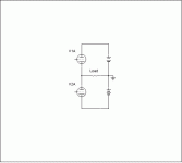
Circlotron should have 2 main problems:
1) output impedance is the double of the Futterman with the same number of tubes because the output device are in series.
2) The max output current is the half of Futterman for the same.
and 4 anodic voltage are necessary.
Here some image got on an old website (here my mirror).
http://www.audiodesignguide.com/doc/aria.html
Attachments
Last edited:
Why do you say (2)? Let's assume there are just two output tubes in each case (circlotron or Futterman.) In each case the maximum output current is simply that set by the maximum current Imax that each tube can pass. In the Futtterman, just as in the circlotron, at any given point in the peak or trough of the waveform either one tube or the other, but not both, are conducting.Circlotron have 2 main problems:
1) output impedance is the double of the Futterman with the same number of tubes because the output device are in series.
2) The max output current is the half of Futterman for the same.
and 4 anodic voltage are necessary.
Here some image got on an old website (here my mirror).
6C33C-B OTL Amplifier - Background and OTL Circuits
Chris
(You didn't complete the sentence in your point number (2), but I am assuming that you meant to say "... for the same number of output tubes." )
Last edited:
Circlotron should have 2 main problems:
1) output impedance is the double of the Futterman with the same number of tubes because the output device are in series.
2) The max output current is the half of Futterman for the same.
and 4 anodic voltage are necessary.
Here some image got on an old website (here my mirror).
6C33C-B OTL Amplifier - Background and OTL Circuits
Actually, it's not really true that the Circlotron has double the output impedance of a Futterman, and I don't think your explanation about the output devices being in series for the circlotron is quite correct either.
First of all, there are really three cases to distinguish, as in the article you linked to:
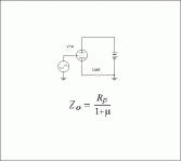
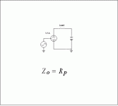
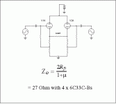
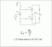
Futterman: Impdeance = Rp/2
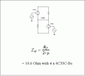
Futterman variation: Impedance = Rp/(2 + 2 mu)
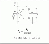
Circlotron: Impedance = Rp/(2 + mu);
The two you were contrasting were probably Futterman variation and circlotron. Anyway, it is not a factor of two between them, and since mu is not very big for a typical OTL output tube, the discrepancy from a factor of two is quite significant. (10.6 ohms versus 6.8 ohms, in the example in the link.)
I'm not sure exactly what you mean by the "output devices being in series" in the circlotron case. But if you consider the upper half of a sinewave signal, then there is essentially a closed circuit comprising one output tube, the speaker and a power suppply. For the lower half of the signal, the closed circuit is comprised of the other output tube, the speaker and the other power supply. (I'm assuming we are essentially in class B, for simplicity. This is not the key issue here.) Anyway, the two tubes are not really behaving as if they were in series.
The operational difference between the circlotron and the Futterman case is really just concerned with where the reference signal ground is located. This is why the output impedances are different. In each case, there is essentially a closed circuit of one output tube, the speaker, and one power supply at any given time in the signal, with the tube and the power supply that is active in the positive half of the signal handing over to the other tube and power supply for the negative half of the signal.
There is a very good article by John Broskie called "Cars, Planes and Circlotrons," at his TubeCAD site (unfortunately currently, and hopefully only temporarily, offline). Anyway, he gives a very nice discussion of the true distinctions between totem-pole and circlotron OTLs.
Chris
Last edited:
The Tubecad article fortunately is back online. Fascinating read. My hands are itching to build a stereo circlotron amp with 16 PL519s...
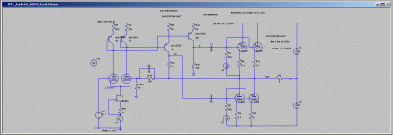
Hybrid ver1a
This is a simple OTL hybrid solution using a current mirror.
Voltage gain 29dB open loop, Rout = 18ohm
Voltage gain 18dB close loop, Rf = 10K / 1Kohm, Rout = 2ohm
The power is not high because the 12AX7 cannot work over 300V but a cascode can solve the problem.
This is a simple OTL hybrid solution using a current mirror.
Voltage gain 29dB open loop, Rout = 18ohm
Voltage gain 18dB close loop, Rf = 10K / 1Kohm, Rout = 2ohm
The power is not high because the 12AX7 cannot work over 300V but a cascode can solve the problem.
Attachments
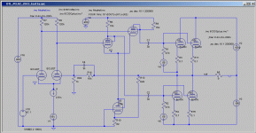
Technics configuration
Here a good simulation of the OTL based on Technics configuration with a second feedback loop to conpensate the voltage gain of the lower output tubes with anode output.
Rout about 2 ohm, input 2Vp to get 50W on 8ohm.
Instead of 2 x PCL82 (triode + pentode) you can use a single 12ax7 and a single 12BH7 like original schematic.
I will continue to simulate this tomorrow.
Attachments
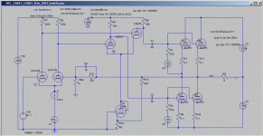
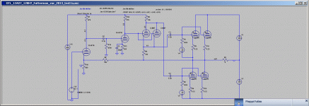
Technics configuration version 2
Here another simulation of the OTL based on Technics configuration with a second feedback loop to conpensate the voltage gain of the lower output tubes with anode output.
Open global feedback 41dB voltage gain, Rout 18ohm
Close global feedback 31dB voltage gain, Rout 1.6ohm, 1% thd at 50W with only 1Vp input
This is based on these design:
http://www.audiodesignguide.com/otl/morikawa.jpg
http://www.audiodesignguide.com/otl/6C33C_2A.GIF
Attachments
Last edited:
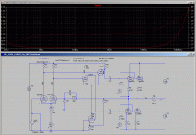
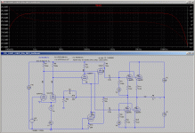
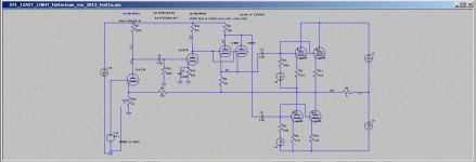
Technics configuration version 2 - new simple
Rout about 0.7ohm
Power 50W with 0.7% THD with only 1Vrms input
Freq. range 0.1Hz to 700KHz at -3dB
Driver stage with only one 400VDC
Global feedback 18dB
Only one interstage capacitor in the signal path
Rout about 0.7ohm
Power 50W with 0.7% THD with only 1Vrms input
Freq. range 0.1Hz to 700KHz at -3dB
Driver stage with only one 400VDC
Global feedback 18dB
Only one interstage capacitor in the signal path
Attachments
Last edited:
Hi Audiodesign !
This last one schematic seems just OK ! ,
but what about insertion of one AF pentode at Amp input gain stage , further DC coupled to 12bh7 inverter /driver stage grid , instead of 12ax7 double triode ? ,for example ef86 or similar one .
Best Regards !
This last one schematic seems just OK ! ,
but what about insertion of one AF pentode at Amp input gain stage , further DC coupled to 12bh7 inverter /driver stage grid , instead of 12ax7 double triode ? ,for example ef86 or similar one .
Best Regards !
Last edited:
Hi Audiodesign !
This last one schematic seems just OK ! ,
but what about insertion of one AF pentode at Amp input gain stage , further DC coupled to 12bh7 inverter /driver stage grid , instead of 12ax7 double triode ? ,for example ef86 or similar one .
Best Regards !
Do you mean use a single pentode instead of the 2 stages with 12AX7 and 12AU7 ?
Do you mean use a single pentode instead of the 2 stages with 12AX7 and 12AU7 ?
Yes !
Where GNFB signal is still injected in relative low impedance cathode node .
-------------------------------------------------------------------------
BTW ,
I think that at least 10% of 6c33c bias need to be accomplished from self bias network in each 6c33c cathode circuit separate , special at that relative high B+voltage of 160VDC , all this just for Amp reliability reasons .
- Status
- Not open for further replies.
- Home
- Amplifiers
- Tubes / Valves
- OTL 2013

