Hi folks,
This is Vincent from Hong Kong and it is my first post in DIY Audio. Nice meeting you guys here.
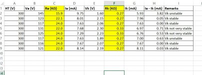
Recently I'm working on adjusting OTK 6J1 biasing voltage. The 6J1 is triode connected and self-biased. I found that the cathode voltage is not stable with certain combination of anode resistors and cathode resistors. By "unstable" I meant the voltage is varying up and down.
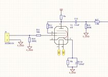
In addition, as the 6J1 is triode connected, the anode current should be the same as cathode current, right? However if Ia-Ik, the result is not always zero. What did I do wrong? Please see the schematic and data below. Thanks guys!
This is Vincent from Hong Kong and it is my first post in DIY Audio. Nice meeting you guys here.
Recently I'm working on adjusting OTK 6J1 biasing voltage. The 6J1 is triode connected and self-biased. I found that the cathode voltage is not stable with certain combination of anode resistors and cathode resistors. By "unstable" I meant the voltage is varying up and down.
In addition, as the 6J1 is triode connected, the anode current should be the same as cathode current, right? However if Ia-Ik, the result is not always zero. What did I do wrong? Please see the schematic and data below. Thanks guys!
Attachments
Could you float the cathode from the bypass cap with a second resistor?
Also maybe varying the 680k grid bias resistor between stages would provide for an outlet albeit a resonant grid.
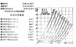
The tubes seem really really nice from the datasheet, so I don't really know.
Also maybe varying the 680k grid bias resistor between stages would provide for an outlet albeit a resonant grid.
The tubes seem really really nice from the datasheet, so I don't really know.
Cathode current = anode current + screen current. The screen does contribute some current.
Also, is the grid leak resistor of 680k too high? You may run into instability issues with such a high grid leak resistor. I am not sure the quoted 1M max grid leak resistance is for pentode or triode connection.
Also, is the grid leak resistor of 680k too high? You may run into instability issues with such a high grid leak resistor. I am not sure the quoted 1M max grid leak resistance is for pentode or triode connection.
Maybe a Schumann resonator printed on the PCB for cathode, g3?
Or maybe alot of discrete logic in the form of caps and resistors between g2 and g1.
Or maybe alot of discrete logic in the form of caps and resistors between g2 and g1.
Last edited:
Could you float the cathode from the bypass cap with a second resistor?
Also maybe varying the 680k grid bias resistor between stages would provide for an outlet albeit a resonant grid.
The tubes seem really really nice from the datasheet, so I don't really know.
Thanks for your reply.
Did you mean to replace the bypass cap with another resistor? I was also thinking the 680k resistor contributes to the instability but the datasheet mentions max 1M.
Yes the grid curves are very evenly spaced, and the sound from OTK 6J1 is very good.
Cathode current = anode current + screen current. The screen does contribute some current.
Also, is the grid leak resistor of 680k too high? You may run into instability issues with such a high grid leak resistor. I am not sure the quoted 1M max grid leak resistance is for pentode or triode connection.
The Ia is actually the current throws through Ra, so it should include the screen current.
What grid leak resistance would you recommend?
Maybe a Schumann resonator printed on the PCB for cathode, g3?
Or maybe alot of discrete logic in the form of caps and resistors between g2 and g1.
g3 is internally connected. hmmm I guess there is no Schumann resonator printed on the PCB.
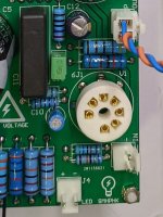
Also, g2 and g1 are quite spaced, pls see the pic attached.
Attachments
Or maybe alot of discrete logic in the form of caps and resistors between g2 and g1.
The definition of "discrete logic" is: "A chip that contains one logic gate or a small number of logic gates."
What do logic gates, which by the way must contain more than only "caps en resistors", have to do with the problem fongshuyuen faces?
And you have NO Schumann resonator as far as I can see. However, you may have oscillations. Have you tried with a lower R1 (1K for example)? Do you see the same thing when C10 is removed? Perhaps you don’t need this capacitor if you have plenty amplification already.
Regards, Gerrit
Regards, Gerrit
Perhaps get rid of R1 altogether if the 6J1 is the tube of interest.
"Caps and resistors":
It would be like an op-amp cathode driver. Introduce "amplification" between grids and allow for a double application of input signal albeit delayed and filtered. It also creates a new resonance between the grids in question. The reason being that sound addition masks the impossible task of resonance subtraction(decimation). Noise addition will change the characterisics enough to temporarily halt oscillative electron flow.
Last edited:
Hi,
Please check your solder joints (heat and reflow the solder)
Pay particular attention to the grounded end of the grid leak resistor, heater and screen connections.
The left hand solder joint on the resistor at the bottom of your photograph looks poor.
Also the solder joint above directly above the 15n capacitor looks poor.
Ignore any posts that seem to indicate the circuit is causing contra rotating electron spin in the ether.
Last edited:
I believe the design is still in the testing phase according to the op and his excel table of data.
Also, if the maximum datasheet self bias grid leak resistance value = 1M then sometimes this value may not be appropriate.
You may not need to alter the value, but trying 500k instead, will not do any harm to a correctly functioning circuit.
Try connecting a suitable value capacitor in parallel to the grid leak resistor, in case of RF oscillation, which perhaps can cause 'motor boating' of VLF oscillation.
You could also check the stability of the HT or B+ supply, for interaction/feedback through the power supply, especially if you are using a cheaply constructed switching power supply. Check you have adequate B+ supply decoupling.
Finally, check the voltage stability of your filament supply, again especially if using a cheap switching power supply (bucking supply)
Last edited:
Higher grid bias resistor will benefit because of the large voltages that can exist on a high resistance albeit at very small currents. The grid will experience less oxidative effects but may still become reduced(plastic like).
The benefit is that the tube can be restored more easily for reintroduction while still acting as a functional input to the electron flow.
Trust me, Superman never reversed the earth only almost stopped it's rotation...
The benefit is that the tube can be restored more easily for reintroduction while still acting as a functional input to the electron flow.
Trust me, Superman never reversed the earth only almost stopped it's rotation...
Last edited:
That is exactly what the op wished to be answered. The value of the anode resistor. Perhaps we can understand that the solution has many answers, but without explanation, the answers are pointless.
Grid leak will never solve "thermal" runaway. It would simply rust away. Thermal being the frequencies defined as the fundamental background of the system.
Grid leak will never solve "thermal" runaway. It would simply rust away. Thermal being the frequencies defined as the fundamental background of the system.
Last edited:
More gibberish Brightcity.
The proper value of anode resistor can be found by drawing a simple load line.
To the OP, I suggest you draw a loadline to find a suitable value Ra.
There are many example of this here, and sites such as the Valve Wizard website, if you need to learn how to do this.
The proper value of anode resistor can be found by drawing a simple load line.
To the OP, I suggest you draw a loadline to find a suitable value Ra.
There are many example of this here, and sites such as the Valve Wizard website, if you need to learn how to do this.
Impossible to define in the circuit it question. The inclusion of a cathode bypass capacitor makes that calculation complicated.
Last edited:
Circuits are no longer "standardized" to the point where tube datasheet values are meaningful. Especially internal capacitances heavily effecting the quoted (1kHz-1.2kHz?) resistances mentioned.
- Home
- Amplifiers
- Tubes / Valves
- OTK 6J1 biasing problems