Hi everyone, sorry for my late reply and thank you all for your generous help. I think I figured out the problem.
1. The input was connected to ground, so the grid leak resistor was bypassed. I replaced the 680k with 100k, it didn't help (as expected)
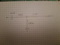
2. I also played with different values of the grid stopper (56k in the schematic): 100k, 1.8k and 1k.
Interestingly changing it 100k or 1.8k did not help, however, when I changed it to 1k, everything works as expected.
I'd like to share my findings with you guys.
First of all, compared with previous 15.9k grid stopper, now the 1k grid stopper behaves in a much stable manner. In addition, there was a 3.82mA difference between Ia and Ik, now the difference dropped to 0.14mA (which could be measuring error or tolerance).
Then I further checked what was happening. I measure Pin 1 (grid), which is connected to the ground through the grid stopper. Grid leak is bypassed as the input is grounded, so theoretically the potential should be 0V. However I had the following findings with different grid stoppers:
100k: Pin 1 -1.4V
1.8k: Pin 1 -0.021V
1k: Pin 1 0V
I can't believe my eyes when 100k of grid stopper is used Pin 1 became so negative that it may draw electrons from the ground to the anode. This might explain why Ia (actually this is the sum of anode current and screen current) is larger than Ik.
I hope my findings would help in the future. And once again, thanks everyone for your input. Really appreciate that.
1. The input was connected to ground, so the grid leak resistor was bypassed. I replaced the 680k with 100k, it didn't help (as expected)
2. I also played with different values of the grid stopper (56k in the schematic): 100k, 1.8k and 1k.
Interestingly changing it 100k or 1.8k did not help, however, when I changed it to 1k, everything works as expected.
I'd like to share my findings with you guys.
First of all, compared with previous 15.9k grid stopper, now the 1k grid stopper behaves in a much stable manner. In addition, there was a 3.82mA difference between Ia and Ik, now the difference dropped to 0.14mA (which could be measuring error or tolerance).
Then I further checked what was happening. I measure Pin 1 (grid), which is connected to the ground through the grid stopper. Grid leak is bypassed as the input is grounded, so theoretically the potential should be 0V. However I had the following findings with different grid stoppers:
100k: Pin 1 -1.4V
1.8k: Pin 1 -0.021V
1k: Pin 1 0V
I can't believe my eyes when 100k of grid stopper is used Pin 1 became so negative that it may draw electrons from the ground to the anode. This might explain why Ia (actually this is the sum of anode current and screen current) is larger than Ik.
I hope my findings would help in the future. And once again, thanks everyone for your input. Really appreciate that.
Attachments
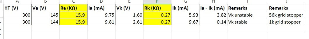
There is a typo in the previous post: 15.9K was the anode resistor. Sorry for the inconvenience.
Bypassed or just open circuit?
This is probably about the simplest circuit that can be built, missing RF lowpassing to safeguard against oscillation.
The datasheet has all you need to find a suitable Ra value, as well as Rk.
What you have documented, is a process of verifying the characteristic curves, instead of using them to design a circuit.
I'm still very very lost, why would anyone try to use a 56k grid stopper? I cant see a reason why you would need to exceed 2k -5k. Even then 2k2 is the largest I have ever required.
Or is this an 'experiment' to see what happens when you make the RC of stopper and Grid so large that it no longer works as a stopper, and begins behaving like an aerial? 😀
Last edited:
I fully understand that I can use the datasheet to design my circuit (more specifically, to find out Ra and Rk). However the problem I was facing was that, when I built the circuit based on the datasheet, the actual measurement did not align with what was shown in the datasheet. This was the reason I seek help from you guys.
Now I understand a grid stopper will affect the performance as it will create a negative potential which draws electrons from the ground to the anode. Lesson learnt. The reason why I used such a high value of grid stopper because I read through some articles in Valve Wizard and Aiken Amplification about grid stopper and Miller Capacitance. In both articles high values of grid stoppers were calculated based on the Miller capacitance existing on the valves. So I truly believe that a high value of grid stopper is a norm. Now I know I was wrong.
FYR:
Valve Wizard:
The Valve Wizard
Aiken Amplication:
Designing Single-Stage Inverting Feedback Amplifiers
Perhaps I spoke in error?
The calculation shown on the Valve wizard pages, includes a capacitor from grid to ground in addition to grid capacitance - to give a larger known capacitance.
E.g. 5pF grid Capacitance, plus 200pF placed in parallel to the grid leak resistance. Then the resistance is calculated taking the sum of capacitance into account.
I prefer to think of this stopping resistance as the total input resistance, which forms and RC low pass circuit.
Thus, I will take this resistance total and split it into 2 parts, an input resistance (useful for defining the High pass turnover frequency with a DC blocking input capacitor), and a stopping resistance right next to the grid connection.
The node where these two resistances are joined is where the grid leak resistance is connected.
In this case then, an input resistance of 50k, with an input capacitor of 0.22uF would give about 15Hz low frequency cut off. Then the grid leak resistance, say 500k, followed by a small stopper resistor at the grid (say 2k2).
The grid then sees about 52k forming an RC low pass with the grid capacitance, and whatever capacitance is in parallel with the grid leak resistance.
You show neither Ri (input resistance) or input capacitance, or indeed capacitance in parallel with the grid leak in your schematic, so one assumes that you do not have them in circuit.
Therefore any DC imposed on the input to the circuit, will cause bias point to be other than expected - a time varying DC input, will show as instability of the bias point.
Hi mondogenerator,
Thanks for your reply. Yes, you're right, we can use a LPF before the input. However I think you misunderstood the Valve Wizard's calculation - the 200pF before grid 1, was the "equivalent" capacitance seen by grid stopper. It is a "magnified" capacitance between the pins, so the author makes use of this capacitance and forms a LPF to filter out unwanted high frequency signals in order to prevent oscillation.
Please correct me if I'm wrong. I'm no expect in the electronics field.
It's not. It's an enlarged value to account for parasitic capacitances.
If I recall Merlin suggests using an additional capacitance in parallel to the grid in order to create an RC time constant which rejects radio frequencies.
Morgan Jones makes very similar suggestions in his books
I am no expert in valve technology but I am an electronic engineer by trade with about 10 years experience in my field of power electronics.
Now that does not make me an expert, or even a good engineer. I make many mistakes and have been proven in error hundreds of times. That is the nature of learning, it never ceases.
However, the lack of DC blocking capacitor at the input to the circuit, and also lack of capacitance across the grid leak resistor, leaves opportunity for DC transients and RF pickup to destabilise the circuit.
Of course, if I am entirely wrong, or misleading you, I would welcome correction by one of the many extremely experienced experts here
I sincerely recommend a DC blocking capacitor as shown in the Aiken Amps pages you linked to earlier - unless you are transformer coupling the input and can guarantee no possibility of DC entering the input
Last edited:
- Home
- Amplifiers
- Tubes / Valves
- OTK 6J1 biasing problems