That generally means that the driver IC failed and caused the opto-coupler to fail. Remove the driver IC and measure the resistance from leg 1 to all other legs. It should be in the mega-ohm range if I remember correctly.
Sorry for delay in replying, I could not do it before ..
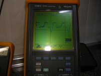
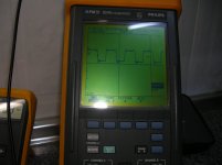
The first photo is the square waveform corresponding to pin 1 of U10, and the second picture corresponds to pin 1 of U6
The first picture, makes a triangular ridge, ranging at the bottom of the square wave, and the second picture, no.
Perry what do you think? Do you think I connect the red and black wires believes voltage rail?
Attachments
My Hameg, I gave it to my family, because I, I took up so much space, and I have no place where I could have it.
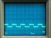
I checked the waveforms, contrasting with other amplifier bd other works properly, (one T1500BD) and look good, therefore, this oscilloscope (philips-fluke) seems to work well.
So I decided to connect the red and black rail voltage cables, and have connected the amplifier, but I had no luck ...
When connected, Q12 has exploded, burning also Q26, Q107, Q108 and Q109.
any ideas?
In the future, do not directly connect the red and black wires until you know that the amp is working properly. To help save the output transistors, insert a current limiting resistor in-between either the red or black wires and the board. Another option is to use a battery. A small 9v battery is enough to allow the amp to produce low power audio. With that battery, there is virtually no risk to the output transistors.
Okay, thanks for the info, Perry.
Tomorrow I will install the new FETs, and will continue taking measurements and looking for possible failures ...
Tomorrow I will install the new FETs, and will continue taking measurements and looking for possible failures ...

Hi again, and sorry for taking so long to get back to this thread.
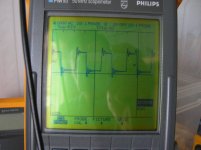
Well, Perry was right, I did not well adjusted the oscilloscope, in their correct settings.
Once this is done, the Square waveforms look good, all FETs that stage, were replaced by new ones.
By connecting the amplifier, everything seems correct, except 14.35 volt output audio ...
any ideas?
Well, Perry was right, I did not well adjusted the oscilloscope, in their correct settings.
Once this is done, the Square waveforms look good, all FETs that stage, were replaced by new ones.
By connecting the amplifier, everything seems correct, except 14.35 volt output audio ...
any ideas?
Are you saying that you have 14.35v of DC offset measured directly across the speaker terminals?
Ok
U17:
pin 1: -0,045
pin 2: 0
pin 3: 0
pin 4: -9,79
pin 5: 0
pin 6: -0,9 ..... -1,75
pin 7: 9,99
pin 8: 0,6
U17:
pin 1: -0,045
pin 2: 0
pin 3: 0
pin 4: -9,79
pin 5: 0
pin 6: -0,9 ..... -1,75
pin 7: 9,99
pin 8: 0,6
Perry big! I discovered that R35 was open!
I installed another 100K resistor because I have none of 121K in my closet.
Now, the voltage at the output terminals of audio is 0.068 V.
Tomorrow, I'll finish to test the amplifier with an audio signal in the input audio, today, it's too late ...
Thank you very much again, Perry, for your great help!
Tested for one hour at medium power level, and perfect performance.
Only one little thing for me ....
When acting on the 0/180 phase switch, the amplifier goes into protection mode the red LED lighting up continuously.
rare?
Protection mode disappears when the amplifier is turned off, and on again ...
Only one little thing for me ....
When acting on the 0/180 phase switch, the amplifier goes into protection mode the red LED lighting up continuously.
rare?
Protection mode disappears when the amplifier is turned off, and on again ...
There is likely significant DC offset between the two positions and it's causing the amp to produce a strong transient pulse and that's causing it to go into protect.
- Status
- Not open for further replies.
- Home
- General Interest
- Car Audio
- other rockford fosgate 1500bd