Tyimo said:Hi!
I have to recompose my previous question:
I know the Ohm's Law: V=I*R that would give me the source voltage, but what would be the best supply voltage for (with) 1-2 V on the source?
(if my EI core choke would have RDC 0,5-1R and I would like to use 2A bias)
Tyimo
Seems you can use anything reasonable as long as it meets your target ouputpower and you recalculate the bias resistors.
Thanks, Thanks, Thanks, a lot Mads!!!😉
Now I understand how the OTA works!
But if I use this kind of calculations, for my choke loaded version I would need a choke with Rdc 5R for 3A bias!?! I think it is not good for a ca.50% efficiency amp....
BTW: the attached schem's values, with the BUZ900 is so different from yours because the BUZ900 has lower Gate-Source cut off voltage (1.5V max) it isn't it?
Thanks again!
Tyimo
Tyimo said:Thanks, Thanks, Thanks, a lot Mads!!!😉
Now I understand how the OTA works!
But if I use this kind of calculations, for my choke loaded version I would need a choke with Rdc 5R for 3A bias!?! I think it is not good for a ca.50% efficiency amp....
BTW: the attached schem's values, with the BUZ900 is so different from yours because the BUZ900 has lower Gate-Source cut off voltage (1.5V max) it isn't it?
Thanks again!
Tyimo
You need to recalculate the Vsource (bias resistors) to get what you want. If your choke has 1R and you want 2A bias, you need 2V at the Source.
Yes, the difference is mainly the mosfet type 😉
I have to leave now, but in the evening I will come back.
It looks like so, that the calculations methode is yet working!!
With 9V supply I would get ca 5-6W!😉
Thanks and greets:
Tyimo
It looks like so, that the calculations methode is yet working!!
With 9V supply I would get ca 5-6W!😉
Thanks and greets:
Tyimo
Biasing a choke loaded circuit is quite different from biasing resistor or CCS loaded circuits.
The choke swings the negative halfwave by itself thanks to the inductance.
Lets say we have a +20V rail and drop 2V across the choke (copper losses), the circuit can still swing 36V peak to peak (theoretically).
This is the biggest benefit in using chokes and transformers instead of resistors and CCS´s.
For further information about inductive loads, talk to the tube guys. They do this kind of stuff every day🙂
Thanks Fuling!
I think I will be lost here...... I thought I understand alrady, but not. 😉
Tomorrow I will try again
Greets:
Tyimo
For further information about inductive loads, talk to the tube guys. They do this kind of stuff every day
I think I will be lost here...... I thought I understand alrady, but not. 😉
Tomorrow I will try again
Greets:
Tyimo
Maybe you can try ZASA (zero amplifying stage amplifier). This might be the next challenge after successful solution of OTA.
Hi!
I will try to invitate here Circlotron, Who has already succesfully built an amp with choke loading. Maybe He can help me or us.
Tyimo
I will try to invitate here Circlotron, Who has already succesfully built an amp with choke loading. Maybe He can help me or us.
Tyimo
Tyimo: Do you already have the chokes or are you going to wind your own?
If you have them, let us know the DC resistance. Then we can help you calculate what bias you need.
If you have them, let us know the DC resistance. Then we can help you calculate what bias you need.
Hi Fuling!
I found a transformator and choke making workshop and I will buy my chokes there. I hope that to Monday I will know the correct datas of my chokes. Untill that time I could say the chokes DCR is ca. 1 Ohm.
So, we could calculate with this number now.
I would like to use 12VDC (battery) or ca. 16VDC (a 12VDC transformator) supply voltages and IRFP 044N or 240 MosFets.
Thanks for your help!
Greets:
Tyimo
good questions
Hi!
After a long search in the forum about the Choke Loaded Source Follower Calculations (CLSF-amp) I found not very much usefull answers, rather good, but not answered questions.😉
Here are some from JoeBob's questions:
I found only one usefull info in the "load on source follower choke or mosfet?" thread, wher AudioGeek asked for an amp with: 20vdc supply, a 3A bias, 100mh 1ohm choke.
Here is Circlotron's answer:
So, the questions are not 100% answered yet.
Fuling, we need your help!!!😉
Back to my amps parameters:
120mH 1RDC 4A choke. I would like to try with +12Vdc supply(battery) or with +16Vdv (transformator) voltage and 2.5-3A bias.
But +24Vdc is also possible to me( double battery 😀 )
Greets:
Tyimo
😀
Hi!
After a long search in the forum about the Choke Loaded Source Follower Calculations (CLSF-amp) I found not very much usefull answers, rather good, but not answered questions.😉
Here are some from JoeBob's questions:
Well, I always wanted to choke load a source-follower, and now I find myself building a headphone amp for my 32Ohm grados, and I thought I might as well do just that. Ok, my question is, if I use a IRF510 with a single suply of 12V (running of a large battery I have) and would like a bias current of say 500mA,
1, How do I go about choosing what choke values I need? Do I just choose a value of mHs that doesn't roll-off frequencies with an impedance of 32 ohms? And, as for the resistance, this will set the bias current, correct?
2, Now, do I choose a choke, and then set the voltage at the source to have the desired current run through whatever resistance the choke is? If so, then wouldn't I just be throwing away voltage if the source isn't at 1/2 the suply voltage?
3, Otherwise, do I choose a choke with a resistance so that at 1/2 the suply voltage there will be say 500mA running through it?
I'm not too sure on what are the importantfactors of choke loading a source-follower, so any other help would be apreciated.
I found only one usefull info in the "load on source follower choke or mosfet?" thread, wher AudioGeek asked for an amp with: 20vdc supply, a 3A bias, 100mh 1ohm choke.
Here is Circlotron's answer:
3 amps will let you swing to -24v into 8 ohms The supply rail will need to be +24v plus a couple of volts extra so the mosfet when swinging positive doesn't have to turn on too hard, going into it's nonlinear region, but don't go nuts. I use 27.7 volts @ 3.5 amps, 80mH.
So, the questions are not 100% answered yet.
Fuling, we need your help!!!😉
Back to my amps parameters:
120mH 1RDC 4A choke. I would like to try with +12Vdc supply(battery) or with +16Vdv (transformator) voltage and 2.5-3A bias.
But +24Vdc is also possible to me( double battery 😀 )
Greets:
Tyimo
😀
I don´t quite undestand exactly what it is you want to know.
This is really very simple; Build the follower with whatever supply voltage you decide, connect the Mosfet´s gate to a variable bias voltage divider thorugh a, say, 100k resistor.
Make sure you bias voltage can be adjusted between 3 and 9V or so. Start at the lower end (mosfet should be cutoff at 3V) and then slowly increase the voltage (and current) until you heatsinks get uncomfortably hot, then back off a bit😀
This is really the best way to go, choose the rail voltage based on how much power you want and then run as much current as your heatsink can handle.
The mosfet need about 4V between gate and source to conduct, then add the voltage across the choke at idle (1,5V for a 0,5R choke and 3A). In this case you need about 5,5V bias voltage, but the only way to get it where you want is to use a variable voltage divider.
If you remind me tomorrow I can draw a schematic for you.
BR
/Daniel
Hi Fuling!
Thanks for the answer!
So, you say the with a choke loaded source follower we needn't care about the source voltage if it is not at 1/2 the suply voltage, because the inductor can swing a lot. O.K. I Understand.
I made 2 version of the Choke Loaded OTA. Please look at, is it O.K , or not.
One more question: I need 200K Zin. It would be good for my tube pre. How can I adjust it the best way??
I also would like to know your version!😉
Here is mine similar to the TubeCad's schematic.
Greets:
Tyimo
Attachments
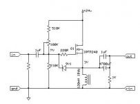
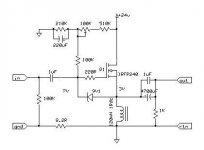
I like the second version best, where the mosfet is separated from the voltage divider by a 100k resistor.
Both should work pefectly fine!
I hope you understand the size of the required heatsinks!!
63W is a lot of heat for one mosfet to handle.
This follower should be able to put out 27W into 8 ohms, think again if you really need all that power.
If you lower your rail voltage to 16V you will still get over 10W out but "only" 39W of heat in the mosfet.
If you go for 16V you can also decrease the current to 2-2,2A which would make the whole thing run much cooler.
Tyimo said:
One more question: I need 200K Zin. It would be good for my tube pre. How can I adjust it the best way??
Tyimo
Input impedance is essentially the resistor from the voltage divider to the gate (100K in this case) Put in a 220K and your tube pre will be 🙂
The idea of using an inductor has some merit; however, you should investigate the size of a 120mH, 3 or 4 amp inductor. It will be very large and heavy. Inductor physical size is proportional to the product .5*L*I*I.
Hi Mads and Fuling!
Thanks for all the help!
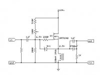
I understand the input imp. in the second schematic, but what is the situation in the first schem? (TubeCad's arrangement)
Which one is the imput imp. resistore? The lower 200K?
What value need for the resistore befor the input cap to the ground?
Yes, you are right! I think I will try a low and a high powered version. Heatsinks are no problem....😀
Tyimo
Here is the TubeCad's style arrangement schem.
Thanks for all the help!
Input impedance is essentially the resistor from the voltage divider to the gate (100K in this case) Put in a 220K and your tube pre will be
I understand the input imp. in the second schematic, but what is the situation in the first schem? (TubeCad's arrangement)
Which one is the imput imp. resistore? The lower 200K?
What value need for the resistore befor the input cap to the ground?
I hope you understand the size of the required heatsinks!! 63W is a lot of heat for one mosfet to handle.
This follower should be able to put out 27W into 8 ohms, think again if you really need all that power.
If you lower your rail voltage to 16V you will still get over 10W out but "only" 39W of heat in the mosfet.
If you go for 16V you can also decrease the current to 2-2,2A which would make the whole thing run much cooler.
Yes, you are right! I think I will try a low and a high powered version. Heatsinks are no problem....😀
Tyimo
Here is the TubeCad's style arrangement schem.
Attachments
Sawreyrw!
We are using EI core chokes, so the size is not a problem to us, it isn it Fuling?!?😀
Greets:
Tyimo
The idea of using an inductor has some merit; however, you should investigate the size of a 120mH, 3 or 4 amp inductor. It will be very large and heavy. Inductor physical size is proportional to the product .5*L*I*I.
We are using EI core chokes, so the size is not a problem to us, it isn it Fuling?!?😀
Greets:
Tyimo
Tyimo said:
Tyimo
Here is the TubeCad's style arrangement schem.
Don't do it like that.
- Status
- Not open for further replies.
- Home
- Amplifiers
- Pass Labs
- OTA - One Transistor Amplifier