Nice 🙂 Looks like you are quite serious about your audio gear 😎
Are you using 19" pro racks?
Hehe... 😀 47V@3,5A is one hot cookie, no wonder it sounds good. You must be getting near 10W output before distortion takes over.. What are those speakers in the background?
edit: starting to think of it, you are running your transformer VERY hard.. I would have specified 2 of those for a 175W/ch OTA. I would at least use a small fan to get some air circulation around it. Would be a shame to burn such a nice transformer..
Hi Mad_K ,
Are you using 19" pro racks?
Yes I do , I could get them a longtime ago to put them in my "music" room ...
.. What are those speakers in the background?
This is my other Audio system .
The woofer is a PR38 AUDAX speaker , the medium is a HD17HR37 AUDAX speaker ant the tweeter is the FOSTEX FT90 .
Those speakers have all ther dedicated amp and are driven through an KANEDA actif crossover system .
I have got 2 * 150 W ( AB ) for the woofer ,
2 * 20 W ( A ) for the medium
2 * 15 W ( A ) for the tweeter ,
and all this sounds quite well . Ther is a real physical impact with a 38 cm !
edit: starting to think of it, you are running your transformer VERY hard.. I would have specified 2 of those for a 175W/ch OTA. I would at least use a small fan to get some air circulation around it. Would be a shame to burn such a nice transformer..
Thanks for this warning , I will also check the 10 ohm resistors .
I could eventually increase their value to drop the bias current .
Best regards ,
@ + Philippe.
Are you using 19" pro racks?
Yes I do , I could get them a longtime ago to put them in my "music" room ...
.. What are those speakers in the background?
This is my other Audio system .
The woofer is a PR38 AUDAX speaker , the medium is a HD17HR37 AUDAX speaker ant the tweeter is the FOSTEX FT90 .
Those speakers have all ther dedicated amp and are driven through an KANEDA actif crossover system .
I have got 2 * 150 W ( AB ) for the woofer ,
2 * 20 W ( A ) for the medium
2 * 15 W ( A ) for the tweeter ,
and all this sounds quite well . Ther is a real physical impact with a 38 cm !
An externally hosted image should be here but it was not working when we last tested it.
edit: starting to think of it, you are running your transformer VERY hard.. I would have specified 2 of those for a 175W/ch OTA. I would at least use a small fan to get some air circulation around it. Would be a shame to burn such a nice transformer..
Thanks for this warning , I will also check the 10 ohm resistors .
I could eventually increase their value to drop the bias current .
Best regards ,
@ + Philippe.
Hi!
Hello!
I'm new here, and need some help.. i'm thinking in make OTA (in the simplest version) or the SEWA amp, but i dont know if is possible link any to one bass guitar. Also, i dont know if thse are the best circuits for this application (a instrument amplification, SS components and low cost, preferrably), and if (and why) is really necessary a pre-amp (just for tone control or for impedance matching or something like that)?
oh, sorry by the bad english - i've learned by myself along the last years, but i think still isnt enough to express some things clear and exact.. 🙁 just ask and i'll try explain i've trying say
🙂 Thanks!!!!
gminoru
Hi ,
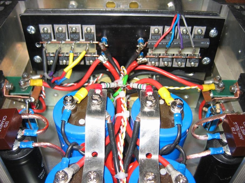
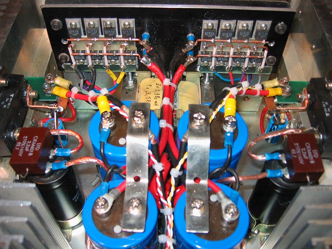
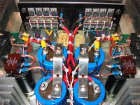
Here we go again , my Amp has been upgraded , and now it looks like this :
The first version of the 10 ohm resistor burned out , so I have put a 100 Watt version . I also added a second transformer and
fast rectifiers bridges on each channel .
The sound is still a delight !
@ + Philippe.
Here we go again , my Amp has been upgraded , and now it looks like this :
An externally hosted image should be here but it was not working when we last tested it.
An externally hosted image should be here but it was not working when we last tested it.
An externally hosted image should be here but it was not working when we last tested it.
An externally hosted image should be here but it was not working when we last tested it.
The first version of the 10 ohm resistor burned out , so I have put a 100 Watt version . I also added a second transformer and
fast rectifiers bridges on each channel .
The sound is still a delight !
@ + Philippe.

Mad_K said:I while back I posted a amplifier design with only one transistor. I named it SEWA (Seven Watt Amplifier).
It seems most people interested in the design actually wanted LESS power (power dissipation I guess).
While the SEWA design has evolved into something different (coming later),
I have renamed this design OTA - One Transistor Amplifier. Attached is the revised schematic.
Why not buy 2 Transistors?
Of course I can see the challenge in making best possible with just one device
but really, why not add one extra helper transistor .. to get some good quality?
Just asking
Originally posted by Mad_K: "It seems most people interested in the
design actually wanted LESS power."
They talk that way until it is time to buy, and then they pick the amp
with more power.
😎
design actually wanted LESS power."
They talk that way until it is time to buy, and then they pick the amp
with more power.
😎
(sorry for my english)
Hi Mad_K,
I have built the " power follower 99" ( Andrea Ciuffoli design) and
have one observation to do.
After a long experimentations ( two years) of listening tests I have found this amp sounds wonderful on the mid and high but sounds also
without any type of punch / slamm on the bass. Big delusion. 🙁
This is not a problem of power, I am sure . I listen at low levels with "easy" speakers ( in mid-field).
I have compared it with a aleph30 and the result is very similar to my ears. Monotriodes also.
Compared with a X-250 the difference is total, another world! One of the best bass I know.
Again I repeat I listen a very low levels.
Is it a sort of "genetic trade/ carachter" of the SE (only output stage
I suppose)?
All the comments are appreciate 🙂
Cheers,
Inertial
Although late for answering this post, I would like to add my 2 cents.
First, guys, forget about 4700uF output cap. Decent solution for an output cap, is three "caps" in parallel.
1-st cap: 33...68uF polyprop cap (closest to the schematics)
2-nd "cap": 16...20pcs of paralleled 1000uF Nichikon KZ (or Elna Silmic)
3-rd "cap": 1 or 2 paralleled 10000uF average quality caps in series with 50mOhms resistor (two 0,1R resistors in parallel).
Whatever your impedance calculations say, adding of the 3-rd "cap" is listenable at bass domain.
Next, NoNFB designs are very sensitive (from BASS point of view) to a kind of output transistors. Bass is getting better along this line: lateral MOSFETs, vertical MOSFETs, silicon BJTs, Ge BJTs. The laterals are "afraid" of current, while BJTs and especially Ge BJTs are "glad to accompany" the current. There is a ground to the fact, that Charles Hansen uses BJTs in Ayre amps. Even if Zout of designs with various kinds of transistors are close to each other, bass signature differs substantially.
Deep NFB designs are also not free from effects of output transistors used. With lateral MOSFETs, even design with 60dB of NFB at 20kHz gives a bit weak bass. Vertical MOSFETs and BJTs are better for bass domain.
PF99 is a great IDEA for SE output stage, but for extracting all potential from it, I have ended up with necessity of some pre stages and some so called "current NFB", with 300MHz BJTs at the output. This allows for great sound.
I am not convinced about your 3 Caps concept.Although late for answering this post, I would like to add my 2 cents.
First, guys, forget about 4700uF output cap. Decent solution for an output cap, is three "caps" in parallel.
1-st cap: 33...68uF polyprop cap (closest to the schematics)
2-nd "cap": 16...20pcs of paralleled 1000uF Nichikon KZ (or Elna Silmic)
3-rd "cap": 1 or 2 paralleled 10000uF average quality caps in series with 50mOhms resistor (two 0,1R resistors in parallel).
Whatever your impedance calculations say, adding of the 3-rd "cap" is listenable at bass domain.
Next, NoNFB designs are very sensitive (from BASS point of view) to a kind of output transistors. Bass is getting better along this line: lateral MOSFETs, vertical MOSFETs, silicon BJTs, Ge BJTs. The laterals are "afraid" of current, while BJTs and especially Ge BJTs are "glad to accompany" the current. There is a ground to the fact, that Charles Hansen uses BJTs in Ayre amps. Even if Zout of designs with various kinds of transistors are close to each other, bass signature differs substantially.
Deep NFB designs are also not free from effects of output transistors used. With lateral MOSFETs, even design with 60dB of NFB at 20kHz gives a bit weak bass. Vertical MOSFETs and BJTs are better for bass domain.
PF99 is a great IDEA for SE output stage, but for extracting all potential from it, I have ended up with necessity of some pre stages and some so called "current NFB", with 300MHz BJTs at the output. This allows for great sound.
My opinion is that one good quality 4.700uF cap is alright for 8 Ohm speaker.
Are you sure you get better results with your way?
I am not convinced about your 3 Caps concept.
Hi Lineup,
Long time no talk.
Capacitive decoupling (i.e. with capacitor) and direct coupling (i.e. without capacitor) perform different sound quality which is subject to individual taste of sound. If capacitor is used in input/output of circuitry, it must form an analog filter, common RC filter, or even LRC filter at output of power amplifier. (e.g. High pass, low pass, full pass, etc…) Becareful to use it as human audible frequency 20Hz-20KHz cannot be cut off. I can see many people repeat and repeat to misuse it, I have no time to comment anymore. Lastly, becareful to use capacitor!
Hi guys ,
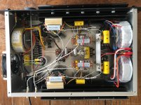
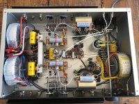
I put some pictures again from my device :
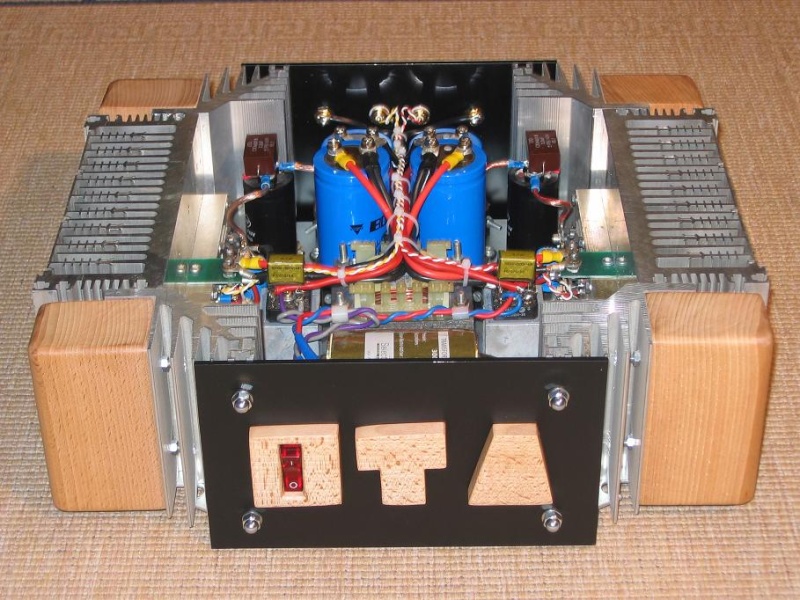
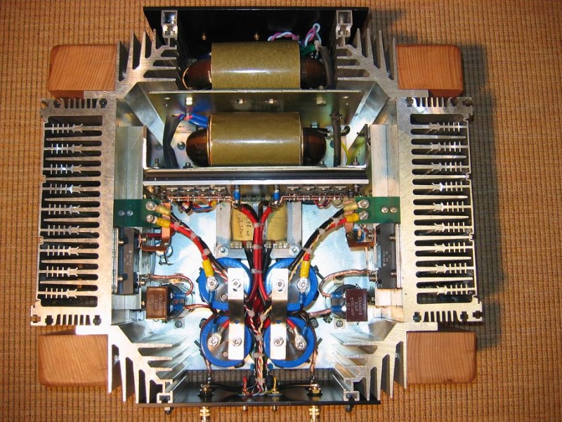
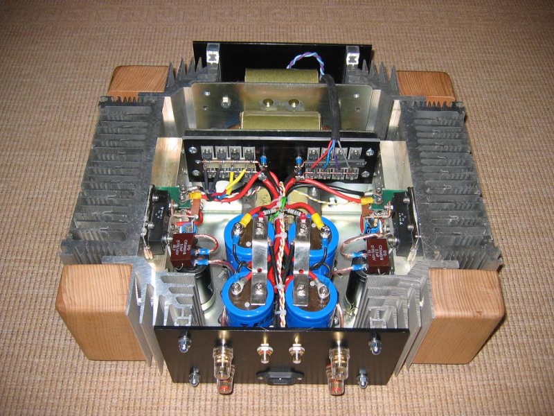
@ + Philippe
I put some pictures again from my device :
@ + Philippe
Attachments
Last edited:

Hey all, I also posted this is the SEWA thread - have upgraded my OTA build to a SEWA build. Halved the cooling requirement and increased from 2.5-watts to a whopping 3.3-watts. What a ride...
Chris
Chris
Attachments

Nice musical heaters !
.
AWESOME amp builds guys ! 😀 😀 😀 😀 😀
How's the listening going on these OTAs ? 😎

Si. 🙂
t.S.E.c
.
.
AWESOME amp builds guys ! 😀 😀 😀 😀 😀
How's the listening going on these OTAs ? 😎
Si. 🙂
t.S.E.c
.
- Status
- Not open for further replies.
- Home
- Amplifiers
- Pass Labs
- OTA - One Transistor Amplifier