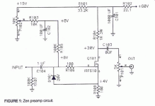
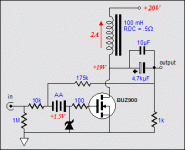
I can't find the schematic of the MU follower Tube preamp.
It is in the Tube Preamp for SEWA thread, in the tube forum.
What do you mean with slightly modified?Where can I find it?
Better PSU and PCB layout.....
Tyimo
Hi!
It is the original BOZ circuit.
No, you needn't change, only if you want a bit better sound!😀
I posted earlyer in the SEWA thread my listening test about the BOZ with 2sk216.
Tyimo
What about this one,can I use this one?
It is the original BOZ circuit.
Do I need to change fet IRF 610 with the 2SK216 and why?
No, you needn't change, only if you want a bit better sound!😀
I posted earlyer in the SEWA thread my listening test about the BOZ with 2sk216.
Tyimo
Tyimo,
I cannot find the connectiong post to your BOZ version - can you please post the schematic or changes again?
I cannot find the connectiong post to your BOZ version - can you please post the schematic or changes again?
Hi Lohk!
My report is on: http://www.diyaudio.com/forums/showthread.php?postid=1046089#post1046089
I changed only the Mosfets. 2SK216 instead of the IRF610.
The schematic remain the same like the original BOZ.
Watch for the different pin layout: GSD!
Tyimo
My report is on: http://www.diyaudio.com/forums/showthread.php?postid=1046089#post1046089
can you please post the schematic or changes again?
I changed only the Mosfets. 2SK216 instead of the IRF610.
The schematic remain the same like the original BOZ.
Watch for the different pin layout: GSD!
Tyimo
I'm not shure, I don't think it would be a very good idea. Have you tried to open them up to see what's inside?
Try to run a few DC amps in each section. It it survives (give it some time 😎 ) , it should be OK You'll get a very nice bias adjustment with that thing 😉
Mads.
Did you help me to adopt this schematic to 50V supply ?
25dB is more then enough for me.
I go to basement to found my UTC chokes because I not sure
the mH and current.
They are air gapped.
Did you help me to adopt this schematic to 50V supply ?
25dB is more then enough for me.
I go to basement to found my UTC chokes because I not sure
the mH and current.
They are air gapped.
OK,
Choke is UTC S-81 two coils in series 100/8mH 2.5A 0.6R
in parallel 25/2mH 5A 0.15R.
I hope that be OK ?
Choke is UTC S-81 two coils in series 100/8mH 2.5A 0.6R
in parallel 25/2mH 5A 0.15R.
I hope that be OK ?
Mads,
I never made any SS amp but this is so simple for start
Here is the article :
http://www.tubecad.com/2004/blog0005.htm
I never made any SS amp but this is so simple for start

Here is the article :
http://www.tubecad.com/2004/blog0005.htm
Hy there ,
I 'm back to give you news of the OTA “improved” Amp.
First of all, I recovered the R-Core transformer of an IGBT amplifier project . This transformer has 2 separated secondaries , whereas the old one comprised one of them, moreover I had to wind whorls with the secondary to obtain the required voltage.
Now i was in order to separate completely the both power supplies chanels , dedicated ground circuits , by taking care to avoid ground loops while wiring . The ground of each oh the 2 amplifier circuits is taken directly on the 2 electrochemical caps downstream, of stronger value than the first (33.000µF against 22.000µF). I also added a connection by screw & bolt on the IRF150 for the maintenance actions.
Small aesthetic relooking to finish on a wooded note.
It now remains to me to listen to it to drip the differences.
Best regards ,
@ + Philippe.
I 'm back to give you news of the OTA “improved” Amp.
First of all, I recovered the R-Core transformer of an IGBT amplifier project . This transformer has 2 separated secondaries , whereas the old one comprised one of them, moreover I had to wind whorls with the secondary to obtain the required voltage.
Now i was in order to separate completely the both power supplies chanels , dedicated ground circuits , by taking care to avoid ground loops while wiring . The ground of each oh the 2 amplifier circuits is taken directly on the 2 electrochemical caps downstream, of stronger value than the first (33.000µF against 22.000µF). I also added a connection by screw & bolt on the IRF150 for the maintenance actions.
Small aesthetic relooking to finish on a wooded note.
It now remains to me to listen to it to drip the differences.
An externally hosted image should be here but it was not working when we last tested it.
An externally hosted image should be here but it was not working when we last tested it.
An externally hosted image should be here but it was not working when we last tested it.
Best regards ,
@ + Philippe.
Wow, cool! What a masterpiece! I think you captured the true spirit if DIY with this one 🙂 What voltage/current/bias are you running? How does it sound (on what speakers) ?😎
Hi Mad_K ,
Thanks for your congratulation .
My new transformer 2 * 36 V / 300 VA provides me 47 VDC , at the bias current is near to 3.5 A .
It sounds really lovely , just with one transistor !
The speakers I use are self made Fostex full-range using the FE208 and an additionnal tweeter FH90 .
Here is a photo so you can see what they look like .
Bye ,
@ + Philippe.
Thanks for your congratulation .
My new transformer 2 * 36 V / 300 VA provides me 47 VDC , at the bias current is near to 3.5 A .
It sounds really lovely , just with one transistor !
The speakers I use are self made Fostex full-range using the FE208 and an additionnal tweeter FH90 .
Here is a photo so you can see what they look like .
An externally hosted image should be here but it was not working when we last tested it.
Bye ,
@ + Philippe.
- Status
- Not open for further replies.
- Home
- Amplifiers
- Pass Labs
- OTA - One Transistor Amplifier
