I don't think these chips are that good for audio. You then have to stop the project. There are probably better ones now.
BGAs are no good friends of DIYers, mate! 🙂It is perhaps a bit late to consider a change of the ADC ... but the new AD4030-24 SAR ADC looks even more interesting than the LTC2380-24.
Hi all,
Still alive..
Sorry to not having big announcement about project progress...
You are right Zfe, there is already some others parts very interesting than LTC2380-24 now.
I looked into it also, and seems at least on paper, very interesting.
I continue to read some thread and posts on the forum, but don't have so much time
for more at the moment. I think to post more on the EOSC10KV4 oscillator new version
I have made to help testing the OSVA ADC design performances.
The OSVA still for me an important project even if the final hardware will take another form.
There is again lot of work...But it's fun and a right mean to learn.
Regards.
Frex

Hello, Frex. I want to understand how did you get so small THD from this ADC.AA2380V1 first THD mesurements
Hello all,
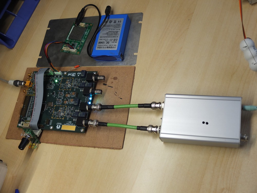
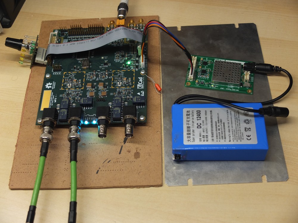
I made some first measurements on the AA2380v1 ADC board of the OSVA.
I made them using the combo AA2380 ADC board and AAPSU01 power supply board.
The source of power is a 12V Li-on battery pack that supply AAPSU01.
I used my EOSC10Kv3 ultra-low THD in differential mode to send it to AA2380v1 input.
The full setup is show on pictures below :
FFT results are below (lin and log scale).
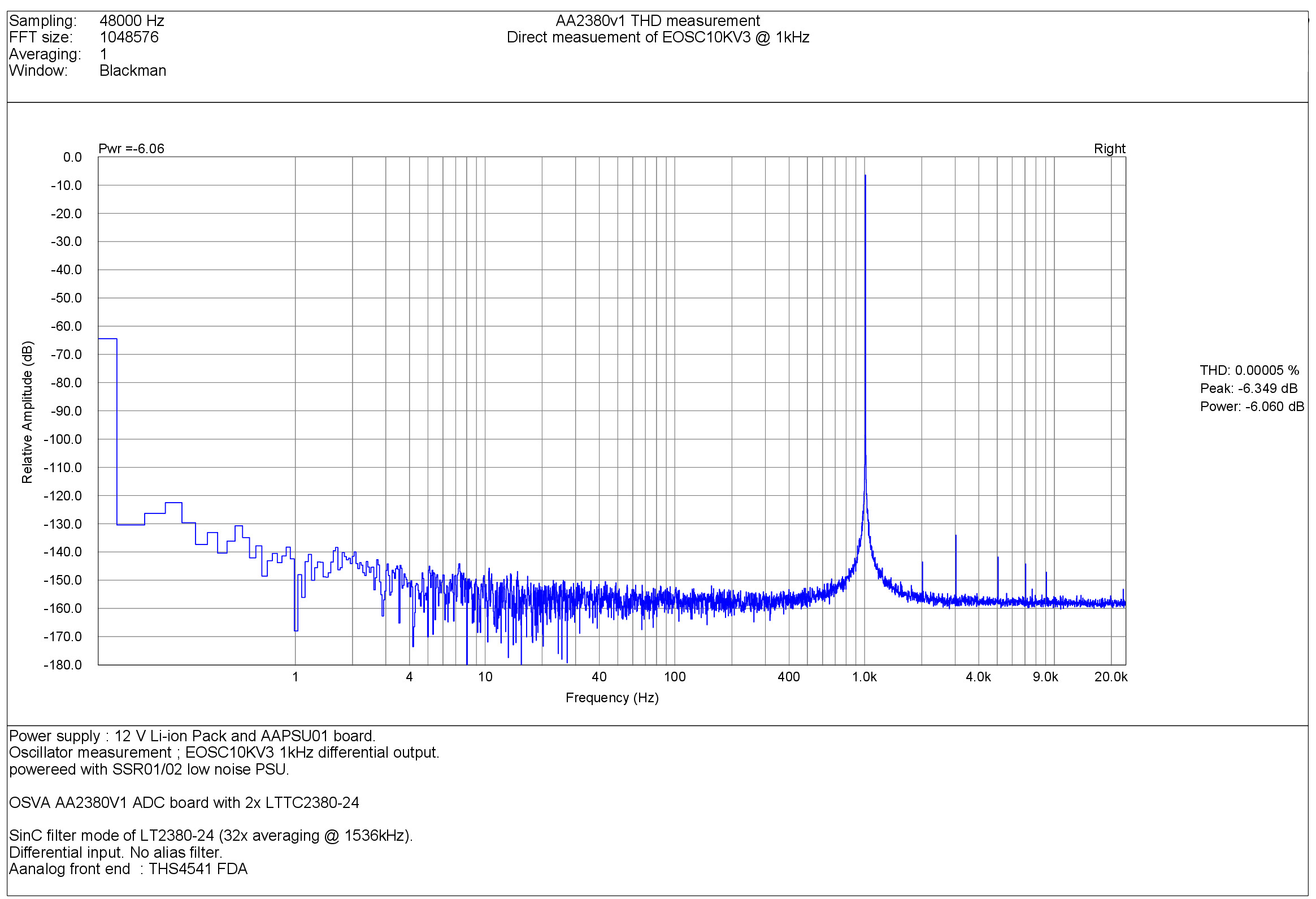
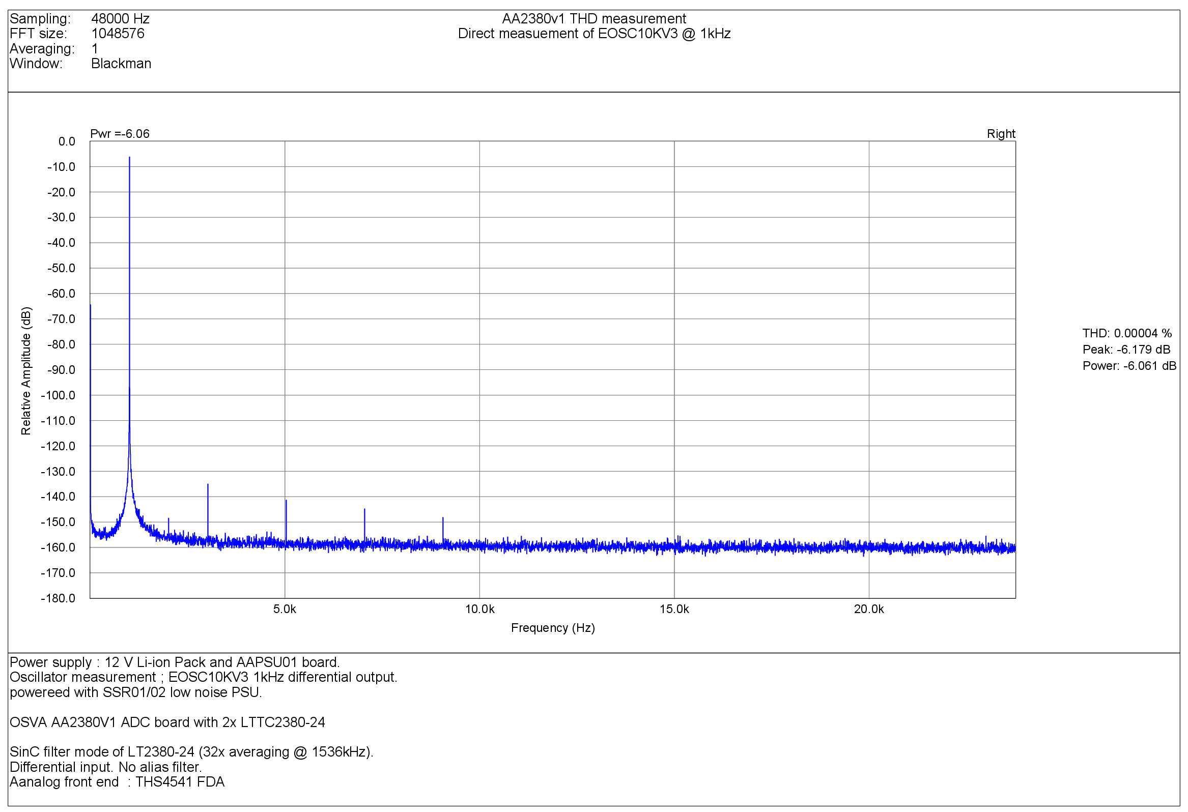
Results are consistent from what i had with modified EVM.
The FFT spectrum is amazingly clean, with no spurious other than THD product itself.
The lower frequency band show absolutely not any trace of main supply ! (no hum noise).
Note that there is no FFT averaging.
The THS4541 input buffer seem promising, but as the input stage can accommodate others, I will try them (ADA4945-1 and OPA1632).
Frex
My best result is -117 db (like it's mensioned in datasheet).
Distortions are disappearing only after -20.
At -6 db its the same level. I'll try to change buffer opamp. But i don't believe it will helps much.
So table correction will help to improve thd up to 20 db.
At -6 db its the same level. I'll try to change buffer opamp. But i don't believe it will helps much.
So table correction will help to improve thd up to 20 db.
Hello Painmailer,
Firt, all measurements I made has been done without any sort of compensation.
Can you point me from which measurements from me you compare your own measurement ?
(you seem to get already a very good THD level).
Maybe you can gave us few more about your design, and also your THD measurement test setup.
Designing an ADC that can get less than ppm level THD is hard to get,
but measuring this level of THD with confidance is it too !
So to try to help you, explain all your detailled test setup,
and if possible post the ADC front-end schematic.
Regards.
Frex


Next problem is noise. I cant get better result even with short circuit inputs of ADC.
My best noise floor is -150 db at 4x decimation on 192 kHz.
ADC works at 1.5MHz with internal averaging to 192 kHz.
My best noise floor is -150 db at 4x decimation on 192 kHz.
ADC works at 1.5MHz with internal averaging to 192 kHz.
Hi folks, hi Frex.
Hope this project have have not died. 🙂
Recently I have finished my own project - high performance USB stereo audio card with ADC based on LTC2380-24 chip and would like to share my tips and experience.
I have used similar to original Frex schematics with ADA4945-1 drivers but with fixed 384kHz input filter.
ADA4945-1 is quite tricky to use and here are my tips:
The measured performance is corresponding quite well to datasheet figures.
And thanks to Fred for his beautiful low-distortion generator, it's quite a piece of gear!


Hope this project have have not died. 🙂
Recently I have finished my own project - high performance USB stereo audio card with ADC based on LTC2380-24 chip and would like to share my tips and experience.
I have used similar to original Frex schematics with ADA4945-1 drivers but with fixed 384kHz input filter.
ADA4945-1 is quite tricky to use and here are my tips:
- Connect chip pad (pin 17) to -V pins;
- While designing PCB, clear all GND layers from copper under input and feedback components of the driver;
- As I have found (the hard way), that accidental short of +V bus to the ground leads to driver chip failure with dead short between +V and +VCL pins. And in my case +VCL was directly connected to +5Vref bus, so +V voltage (7V in my case) was applied to ADC Ref pins. ADC chips survived, but it's highly advisable to put 5.6V protection zener diode on +5Vref bus.
- I have used single +Vocm buffer for both drivers, but put 100R resistor between each driver and buffer output.
The measured performance is corresponding quite well to datasheet figures.
And thanks to Fred for his beautiful low-distortion generator, it's quite a piece of gear!
Intriguing! Any chance for a pro audio ADC, with balanced inputs, high quality filters, conventional samplerates and digital outputs? I would buy it.
living sounds
, do you have any spec in mind?This project is a professional USB audio interface with balanced inputs, balanced and unbalanced outputs which supports 44.1, 48, 88.2, 96, 176.4, 192, 352.8 and 384kHz sampling rates. I am utilizing non-audio ADC and DAC chips of high accuracy (LTC2380-24 for ADC and multi-bit AD5781/AD5791 for 18/20bit DAC respectively).
As for USB to I2S interface, I am using DIYHK XMOS board which has S/PDIF out, but I am not sure yet if it works for recording.
Working on tube front-end for ADC and DAC at this moment. And maybe I should start a separate thread for this.
Just wanted to make some contribution to sleeping project... 🙂
Sounds great! And it looks like it's got everything but the digital output, since for my use case (professional studio) there needs to be a digital output without having to use any USB drivers.
living sounds
, do you have any spec in mind?
This project is a professional USB audio interface with balanced inputs, balanced and unbalanced outputs which supports 44.1, 48, 88.2, 96, 176.4, 192, 352.8 and 384kHz sampling rates. I am utilizing non-audio ADC and DAC chips of high accuracy (LTC2380-24 for ADC and multi-bit AD5781/AD5791 for 18/20bit DAC respectively).
As for USB to I2S interface, I am using DIYHK XMOS board which has S/PDIF out, but I am not sure yet if it works for recording.
Working on tube front-end for ADC and DAC at this moment. And maybe I should start a separate thread for this.
Just wanted to make some contribution to sleeping project... 🙂
What kinds of filters do you use for DC and antialiasing? Are these customizeable (I am sure TNT will have some great input about good sounding filters)?
For me a nice DAC would be an added bonus.
Oh, and yes, please start a new thread. I have been looking for a none delta sigma ADC using a modern chip for a long time.
Yes, start a new thread by all means...
//
Sure thing! 🙂
https://www.diyaudio.com/community/threads/project-iv-usb-sound-card-with-hi-end-twist.403024/
- Home
- Design & Build
- Equipment & Tools
- OSVA - Open source Versatile Analyzer