ok you meens like that ?

for stopper i put a resistor on the base but how many ohms ? 10 ? 100 ?
for stopper i put a resistor on the base but how many ohms ? 10 ? 100 ?
Well I just tested by connecting to the windshield wiper it may improve a little
however there it is I fried the PCB
I had disconnected the amp but by removing the wire grip from the electrolytic capacitor I short-circuited it there was a small spark and voila the two rails are dead I am good for troubleshooting now I do not know for how long I will have
however there it is I fried the PCB
I had disconnected the amp but by removing the wire grip from the electrolytic capacitor I short-circuited it there was a small spark and voila the two rails are dead I am good for troubleshooting now I do not know for how long I will have
i think between + and - of C105
I tested a lot of components on the PCB.
I think C105 and C205 blew.
I haven't found any other blew components yet.
In any case, the output transistors and driver respond well to the diode tester.
I also need to test the amplifier section. After that, I'll switch to the lab power supply. This might prevent further disasters. Since the amplifier was no longer powered, there shouldn't be too much damage, but anyway.
next time i will wait until the capacitors are discharged i went a little fast
I think I'm done for today, I won't have much time to move forward for the rest of the week.
it was during a test directly on the amplifier, I had just cut it there may have been current coming from the amplifier filtering because I made the short circuit just after after turning off the amp I should have waited before removing my grip
afterwards I tested on PCB which is not very reliable the capacitors may not be dead
there is a protection on the regulator which could have come into action and cut the operation maybe even that no components are dead I will have to test it on the power supply of the laboratory already
afterwards I tested on PCB which is not very reliable the capacitors may not be dead
there is a protection on the regulator which could have come into action and cut the operation maybe even that no components are dead I will have to test it on the power supply of the laboratory already
Your style of writing is not easy to understand for me.
Take a break. Perhaps nothing is defective.
Take a break. Perhaps nothing is defective.
Sorry, I use Google Translate, and the results aren't always good.
I have good news: the amplifier is working very well. It was the protections on the two negative and positive rails that must have interrupted operation for a few minutes. This is surprising.
I just received my order, so I'll be able to do some testing in the next few days. maybe this week end
I have good news: the amplifier is working very well. It was the protections on the two negative and positive rails that must have interrupted operation for a few minutes. This is surprising.
I just received my order, so I'll be able to do some testing in the next few days. maybe this week end
I was able to test it with ceramic capacitors on R114-R214 using the wipers It's better than MKP style.
I also slightly modified the resistor values of the RC circuits.
Here it's with a 100pF capacitor, but with a 200pF capacitor, I only have a maximum oscillation of 10mV instead of 14-15mV.
This is on the negative rail; we still see minimal oscillation.
On the positive rail, it's almost perfect.
If I increase the power, there's no instability or more oscillation. I've tested it at 1.6 volts at the input.
To go further, I'll have to solder them directly.
It seems the visible residual of the lower traces just reflects the frequency dependent internal impedance of the supply.
by way of comparison here is the same thing on my first clone of NAP 250 we see a little less oscillation but we also see that the voltage varies more on the square signal the regulator therefore seems more efficient on the new clone
![20250315_145237[1].jpg](https://www.diyaudio.com/community/attachments/20250315_145237-1-jpg.1435434/ "20250315_145237[1].jpg")
![20250315_145249[1].jpg](https://www.diyaudio.com/community/attachments/20250315_145249-1-jpg.1435433/ "20250315_145249[1].jpg")
Not clear which one is which. Settings are the same ?
Where is oscillation ? I see some small overshoot.
Blurring of the lower trace in second picture is noise
or "oscillation" is not visible due to low resolution.
Where is oscillation ? I see some small overshoot.
Blurring of the lower trace in second picture is noise
or "oscillation" is not visible due to low resolution.
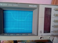
The first two pictures show the negative rail of the regulator with the modifications made on a 10 kHz square wave.
I think there's still a very slight oscillation of 2-3 mV (we're at 100 mV per square for the adjustment).
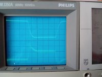
The second picture shows the same thing, but with only 10 mV per square, and the lack of definition masks the oscillation.
The next two pictures show the same thing, but measured on my first NAP250 clone. It's not visible there, but if I look for an oscillation, I still find one, but weaker, around 1 mV. However, I can't be very precise because we're at the limits of the oscilloscope's capabilities.
I don't know if these residual oscillations are due to the regulators or if they are simply small imperfections related to the power supply or my measuring instruments.
I tested another driver transistor, the MJE15031, with which you can obtain less oscillation (with the addition of a 220 pf ceramic capacitor), but in return the voltage is less stable on a square signal, in other words the regulator is less efficient too.
I'm making the final modifications little by little, retesting between each step. If I get this result, I think I'll leave it as is. If it's not good enough, I'll try adding a resistor to the base of Q205 as you suggested.
But with what you've suggested and slightly modifying the RC circuit values, the oscillation is reduced by a factor of 100.
Note that I'm not showing the positive rail because, with the modifications, no oscillation is visible on it.
I think there's still a very slight oscillation of 2-3 mV (we're at 100 mV per square for the adjustment).
The second picture shows the same thing, but with only 10 mV per square, and the lack of definition masks the oscillation.
The next two pictures show the same thing, but measured on my first NAP250 clone. It's not visible there, but if I look for an oscillation, I still find one, but weaker, around 1 mV. However, I can't be very precise because we're at the limits of the oscilloscope's capabilities.
I don't know if these residual oscillations are due to the regulators or if they are simply small imperfections related to the power supply or my measuring instruments.
I tested another driver transistor, the MJE15031, with which you can obtain less oscillation (with the addition of a 220 pf ceramic capacitor), but in return the voltage is less stable on a square signal, in other words the regulator is less efficient too.
I'm making the final modifications little by little, retesting between each step. If I get this result, I think I'll leave it as is. If it's not good enough, I'll try adding a resistor to the base of Q205 as you suggested.
But with what you've suggested and slightly modifying the RC circuit values, the oscillation is reduced by a factor of 100.
Note that I'm not showing the positive rail because, with the modifications, no oscillation is visible on it.
Okay, once the 220pF ceramic capacitors are soldered directly to the PCB and the amplifier is finally wired with the speaker protection, we see oscillation reappear...
Is this due to the long cables I used to connect the ceramic capacitors before? Did they offer a certain resistance? Or is it the speaker ground wiring that's different?
I might try other values besides 220pF, and if that's not enough, I'll place a resistor across the base of Q205 to test, but I think I'm done for tonight, and I'll continue on Tuesday or maybe tomorrow.
ok i try 180 pF but it's not really better
i try to put a trimmer on the base of Q205 and it's worse if i apply a resistor between 0 to 300 ohms
I think I'll try a series resistor across the 10 uf output capacitor to increase the ESR, as Jpk73 suggested.
But I mostly have the feeling I'll have to switch from the ZTX753/653 to the MPSA56/06, like on the original Naim.
I might try the Mj15031 driver again if the series resistor doesn't help, as there was less oscillation with that one as a driver.
I just ran some tests by wiring the grounds differently, and I achieved a significant improvement by separating the high-current grounds from the low-current grounds of the main regulator. I initially planned this on my PCB with jumpers.
There's little oscillation on the square wave signal; we can consider it stable because it damps out in 4-5 waves; there's no visible minimal oscillation behind it.
I tested up to 1 volt at the input on a square wave signal at 1000Hz and 10Khz. In short, I measured at all frequencies; it's stable as is.
Curiously, I had more oscillation on the negative rail and no oscillation on the positive rail. Things are rebalancing, with a similar result on both rails. I think it's a good idea to wire the amplifier ground like this.
I'm going to rework the PCB and replace the 180pF with the 220pf because it seemed to be a little better with that, and I'm going to remove the trimmer.
I'll retest it with new cables, which I need to make.
Afterward, I'll have to test the results by adding the front regulator.
Attachments
- Home
- Amplifiers
- Solid State
- Oscillation into voltage regulator of my new NAP 250 design.