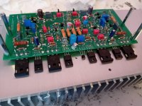
Hello everyone, these last months I started designing a more accomplished NAP250 clone, I may have been too ambitious and suddenly I end up with a small problem of oscillation of the main regulator.
I respected the Naim audio diagram with the difference that I placed the amplifier and the regulator (NAPS) on the same PCB, routing level it was complicated to do.
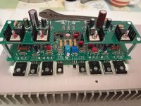
After wanting to improve the amplifier I replaced the MPSA56/06 transistor references with ZTX753/653 which are more robust
the drivers and output transistors were also replaced by
TTC3710B/TTA1452B
and MJW18020 at the output.
The output filtering capacities are at good esr for stability and those at the input too.
everything else works fine the amp the phase compensation etc I even added the TGM10 speaker protection which works and also a front regulator (like the NAP250 DR) but for the moment I dismantled the front regulator to focus on the NAPS which is faulty.
I specify that on laboratory power supply everything worked without problem and the oscillation was therefore not present, I think it is the ripple of the symmetrical power supply which is not supported by the regulator.
do you have any ideas as to the cause of the problem compared to the original design? or do you have a modification to make that could stabilize this problem?
thank you in advance I put you pictures of scope and the new design.
the oscillation is a 150Khz component which makes 100 mv on the negative rail and 50 mv on the positive rail.


I respected the Naim audio diagram with the difference that I placed the amplifier and the regulator (NAPS) on the same PCB, routing level it was complicated to do.
After wanting to improve the amplifier I replaced the MPSA56/06 transistor references with ZTX753/653 which are more robust
the drivers and output transistors were also replaced by
TTC3710B/TTA1452B
and MJW18020 at the output.
The output filtering capacities are at good esr for stability and those at the input too.
everything else works fine the amp the phase compensation etc I even added the TGM10 speaker protection which works and also a front regulator (like the NAP250 DR) but for the moment I dismantled the front regulator to focus on the NAPS which is faulty.
I specify that on laboratory power supply everything worked without problem and the oscillation was therefore not present, I think it is the ripple of the symmetrical power supply which is not supported by the regulator.
do you have any ideas as to the cause of the problem compared to the original design? or do you have a modification to make that could stabilize this problem?
thank you in advance I put you pictures of scope and the new design.
the oscillation is a 150Khz component which makes 100 mv on the negative rail and 50 mv on the positive rail.
Attachments
up trace is the out on a 8 ohms load
down trace is the negative rail out of the regulator (same problem on positive less amplitude)
first picture no signal 2 us for time trigger on the down trace 0,1 v on both
second picture 10Khz signal sinusoïdal 50 us time 0,1v both
down trace is the negative rail out of the regulator (same problem on positive less amplitude)
first picture no signal 2 us for time trigger on the down trace 0,1 v on both
second picture 10Khz signal sinusoïdal 50 us time 0,1v both
sorry I expressed myself badly when I said good ESR I meant good ESR in the sense of a high ESR suitable for a regulator these are not standard capacitors they have an ESR of about 1.8 Ohms measured on a little component tester.
Without knowing the schematic - you can probably add it - this would still be my suggestion.
You can as well poke around with a 1:1 scope probe observing the output at the same time
and see what is going on. Sometimes input capacitance is sufficient to change the situation.
You can as well poke around with a 1:1 scope probe observing the output at the same time
and see what is going on. Sometimes input capacitance is sufficient to change the situation.
The output Q105, 106, 107 etc is complementary darlington or Sziklay.
This can be difficult to tame sometimes. Try base stoppers for Q105, 205.
Did you already probe around ? Are C104, 204 non-inductive ? Small
(ceramic) cap parallel to R114, 214 ?
This can be difficult to tame sometimes. Try base stoppers for Q105, 205.
Did you already probe around ? Are C104, 204 non-inductive ? Small
(ceramic) cap parallel to R114, 214 ?
The small value capacitors are all polypropylene so I assume non-inductive.
there is no capacitor in parallel on R114/R214
i made some measurements but i can't say much about it at the input on C201 i already have a small component at 30 mv (the same one that i found at the output of the front regulator (another PCB) that i have since removed)
on my other measurements i find the same oscillation everywhere for the moment as at the output except at the base of Q205 where it is a little less ample.
What do you mean by stopping at the base of the transistors?
I tried to put a capacitor in parallel on the 47 uf input to double its capacity it didn't change anything in the scope
I have the impression that the solution actually revolves more around the RC circuits on the basis of the drivers I will try tomorrow to place in parallel on R214 a capacitor and on R211 to place a resistor to lower its value and see if that acts on the oscillation.
I will try that tomorrow there it is time to eat ^^ thank you very much for your suggestions because I am navigating a little blindly there I am only a simple amateur in electronics.
If you want to tame the oscillation do not look at the input,
but output and maybe feedback as suggested in post 10.
This means a cap in parallel to R114, 214 may be useful to
try, apart from my other suggestions.
A polypropylene cap is not non-inductive in the general case,
but ceramic caps are - C104, 204.
If you see a nasty oscillation it will show up everywhere, even
on ground wires (and depending on probe grounding position),
so it is necessary to find out where the main source is. This is
in most cases the point with highest amplitude, but not always,
depending on impedance level.
Probing different points in the circuit the results can change, so
watch the ac component of output voltage at the same time.
https://www.mouser.fr/datasheet/2/447/KEM_F3034_R76-3317004.pdf
C103/203 and C104/204 are this type no-inductive in datasheet
https://www.mouser.fr/datasheet/2/440/e_WIMA_FKP_2-1139852.pdf
C102/202 are this type maybe inductive i think
for a capacitor on R114/R214 what capacitance ? 100 pf to 1 nf ? or more ? i have MICA 39pf or styrene
mkp 33pf-47pf-68pf-220p-470 pf
i have 10 pf and a 5 nf that seems to be ceramic type
Ok i put a 560 ohms in parallel of the RC circuit to have 280 ohms it does nothing
i try capacitor in parallel of R214 and there is a very good improvment with 220pf (39 pf don't work and 470 pf don't work too)
i think it's a MKP but i think it's not a non-inductive type here ther result at low current (10Khz 100mv signal)

here at 2 us trigger on B we can see no oscillation with the 220 pf

here with the 10 Khz signal 100 mv it seems to be more good unless the power rail oscillate a little but it around 20 mv only
It's a pleasure to deal with someone competent in electronics, thank you very much in any case I already have an interesting lead without even having dismantled the amp thanks to you
i try capacitor in parallel of R214 and there is a very good improvment with 220pf (39 pf don't work and 470 pf don't work too)
i think it's a MKP but i think it's not a non-inductive type here ther result at low current (10Khz 100mv signal)
here at 2 us trigger on B we can see no oscillation with the 220 pf
here with the 10 Khz signal 100 mv it seems to be more good unless the power rail oscillate a little but it around 20 mv only
It's a pleasure to deal with someone competent in electronics, thank you very much in any case I already have an interesting lead without even having dismantled the amp thanks to you
ok on my first design of NAP250 with original transistor reference it's more stable zero oscillation on square signal I didn't even remember it being this stable.
I need to do some tests on the laboratory power supply but I need to solder and unsolder first. I don't think I'll finish today. I'm going to check my component stocks to see if I need to buy original references in addition to new capacitors for my future tests.
I need to do some tests on the laboratory power supply but I need to solder and unsolder first. I don't think I'll finish today. I'm going to check my component stocks to see if I need to buy original references in addition to new capacitors for my future tests.
I did a test again under laboratory power supply we did not see anything at all no instability it must be said that the laboratory power supply reacts itself and seems to "relieve" the regulator even if suddenly the voltage variations are stronger.
So I placed an order for components with new MPSA capacitors etc.
I could not do more extensive tests tomorrow I will not have time I have to work but Tuesday I could start preparing the PCB while waiting for my order.
Do you think that this oscillation of 20 mv on a square signal is problematic? it is true that on my old design I do not have that
I could test ceramic capacitors of different values when I have my order and I will increase the ESR of the output capacitors by 10uf, finally I will place variable resistors on the RC circuits to see if I can improve things.
If these solutions were not enough I could try a stopper on Q105/Q205 or change transistor references in particular on Q106/Q206 which seems more sensitive to me.
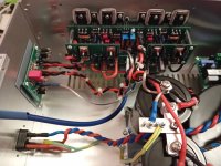
ok so I disassembled the PCB to place it on the test heatsink which frees up the back panel to be able to change components for testing.
i just did my first series of tests:
i changed the 10uf output capacitors which have an ESR of 1.8 ohms for 2.5 ohms of ESR which is less limited
i placed 2000ohm trimmers on the RC networks to vary R111/R211
i added in parallel on R114/R214 grips files to be able to test different capacitor values again.
In total:
I have no influence from the ESR of the 10uf output capacitors or very little
I have a positive channel that gives less oscillation than the other (30 mv against 100 mv)
when I vary R114/R214 there is indeed an influence but insufficient to perfectly stabilize things that said I still get an oscillation of barely 10 mv on the positive rail at rest and it goes up to 25 mv on a 10Khz 100mv signal
on the negative side I manage to go from 100 mv to 80 mv at rest by varying R214.
by adding a capacitor between 39pf and 220pf it improves things again without however completely eliminating the oscillation.
I am waiting for my order of components but the RC networks do indeed have an influence I was wondering about the values of the capacitors of the RC networks would not need to be changed otherwise another possibility would be to try other driver transistors but for these tests I need to have my order.
I see no need to work on the RC networks with R111, 211 and think I did not recommend it.
R 114, 214 are in the feedback circuit and any change will change the output voltage. I did
not recommend it. I recommended to try ceramic caps in parallel. To be even more effective
these can be connected to the pot RV102, 202 wipers, not just the left side of resistors R 114,
214.
I also recommended to try base stoppers.
- Home
- Amplifiers
- Solid State
- Oscillation into voltage regulator of my new NAP 250 design.