The amp lives! However, the left channel doesn't have any noticeable output.
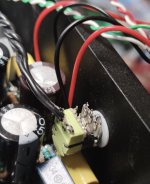
Traced the signal chain, and the volume pot is behaving a bit weird. It's one of them with a switch in it, pic attached.
It's impossible to measure at the input on the board (too much stuff in the way), so I just desoldered everything and intend to go through and "map" the pins. Might temporarily wire up individual pots for L and R channels to eliminate variables.
Attachments
Absolutely going to try this! Wouldn't mind messing with this design a bit once I get it running as it should.A. Sometimes, it can be helpful to run a simulation program, with the negative feedback Disabled:[...]
UPDATE: I've been plugging away at this amp for the past two days, and I'm pretty over it at this point 
I ran through it and cleaned up the wiring, added some JST connectors from the pot to the board to ensure solid, secure connections. Also replaced C6 with a 100uF cap -- the one in there was 68uF, go figure.
Just hooked it up with my signal generator and turned it on; and the thing let out some ungodly high frequency stuff once it got up to temp. A screeching, slowly declining sound which seemed to randomly jump up and down in frequency, not unlike that cartoon noise of a bomb falling. Figure maybe the 100uF cap i slapped in there was bad?
Regardless, I'm tired of it at this point. It's a real hassle getting the board out, and i can't do anything with it in situe. Going to sit down in KiCad and draw up an RH84 monoblock with separate power supply to get this off my mind for a bit.
Next step is putting the 68uF cap back in, but i'm not doing that today
Swapped how? The secondaries haven't been touched, so they're good. The primaries are hooked up the way they were previously, but I think i swapped polarity on the left channel input. Could that be it?got the primary or secondary windings of the opt swapped
If the input is polarity swapped you will nothing out of that channel as you are grounding the input!
If you swapped the HT lead with the plate lead to the primary to the opt then negative feedback becomes positive. You will get all sorts of square wave type oscillations.
Ah -- gotcha. Going to double check things.If you swapped the HT lead with the plate lead to the primary to the opt then negative feedback becomes positive. You will get all sorts of square wave type oscillations.
Being as this is my first time testing a tube amp, i have a few questions:
1. Is it safe to run the amp without any tubes in it, just to measure voltages?
2. Being that SE amps are sensitive to output impedances, do the outputs always have to be hooked up to a load while running?
3. Along that line, do the inputs always have to be connected while the amp is running or can they be left floating?
4. How does one tell which way is the "right" way round on OPT's? None of the eyelets on the OPTs are marked in any way, so it's hard for me to tell.
I'm an electrical engineer by trade so proper safety procedures will be followed, but SE amps are still a mystery to me. Just don't want to make any costly mistakes before i either get this running or draw up a new circuit for it.
1) Yes providing the HT supply does not exceed the rating of the caps.
2) Yes you can damage the output tube if there's no load and there's a large input signa;. You can use a dummy load does not need to be 8R. Even 47R is much better than nothing. You can also short the output (unlike a transistor amp).
3) Can be left floating and should be OK as long as the input tube grid has a resistance path to ground.
4) You know if its wrong way round! You can disconnect the negative FB and check this signal is in phase with the signal on the grid or cathode of the tube the FB was connected to.
Last edited:
Gotcha. I have a pair of 10k 10W resistors i should be able to use, then.2) Yes you can damage the output tube if there's no load and there's a large input signa;. You can use a dummy load does not need to be 8R.
I feel like I do, yes4) You know if its wrong way round!
 . But -- as long as the primaries are connected the right way, the orientation of the secondaries should only affect speaker phase, no?
The feedback is connected to the speaker. So orientation of the secondaries effects both the speaker phase and the feedback phase. 10K is too high for a load - no bigger than 47R I would say.
You could use the 10k resistor to shunt the OPT primary (5-k allready suggested in #60, but 10k 10W will do just as well)
Ah, of course it does. Going to try flipping the primaries when i get home and see what happens.The feedback is connected to the speaker. So orientation of the secondaries effects both the speaker phase and the feedback phase.
What would shunting the primary do? IIRC #60 recommended doing so in the simulations to accurately measure low end response. Is shunting just placing a resistor across, then?You could use the 10k resistor to shunt the OPT primary (5-k allready suggested in #60, but 10k 10W will do just as well)
IT'S ALIVE. Been listening to it for the past hour or so. Unfortunately I only have some Argon Alto 4's to demo it with at the moment, but whatever's there sounds good.
It was a case of the flipped primaries, as baudouin0 rightly guessed.
For now the plan is to leave it as is and turn my focus to the speaker build, so that I'll be able to properly demo it in a setup it's well suited to.
Thank you all for bearing with me, my stupid questions and beginner mistakes. Special thanks to baudouin0, 6A3sUMMER and mdpaudio!

- Home
- Amplifiers
- Tubes / Valves
- Oscillating/motorboating SE EL84 Amp