Sure thing!
Also, didn't have any 12AU's laying around, so decoupling it is. I assume the caps shouldn't be polarized?
Also, didn't have any 12AU's laying around, so decoupling it is. I assume the caps shouldn't be polarized?
I guess you used the 600 Ohm generator to the 47k series resistor to the primary winding.
Then I guess you measured across the primary on channel 1, and then across the Loaded secondary on channel 2.
This needs to be a bare bones measurement, with no other circuits connected to the transformer.
An output transformer with 280 degrees phase shift from primary to secondary at 14kHz, or 16kHz, or at 20kHz . . .
Well, that means one of two things:
1. You did not connect the primary and secondary so that they are close to In-Phase at 1 kHz (near zero degrees). Measure there first.
Or
2. Your transformer is not very good to use an EL84 in Pentode mode to drive it.
If you have to re-connect your transformer so that it is In-phase at 1kHz; then when you re-measure the phase shift at high frequencies . . .
The new measurement reading will become: 280 degrees - 180 degrees = 100 degrees phase shift at high frequencies.
Please let us know the 'new' high frequency phase shift degrees number.
Lets try an experiment:
Disconnect the EL84 screen from B+.
Then reconnect the EL84 screen to a 100 Ohm resistor, and connect the other end of the 100 Ohm resistor to the plate.
Now you are triode wired.
We just went from 40k Ohms plate rp, to 1700 Ohms rp.
Less maximum power output, but the oscillations might stop.
If they do stop, perhaps we can make some changes to get back to Pentode mode.
We will get it up and running, and then you will have fun.
Do not give up.
For Newbies that have never built a vacuum tube amplifier . . .
PCB make it easier to build.
Point to point wiring may have mistakes in wiring, but it is easier to troubleshoot, fix, and modify.
Just my experience.
Last edited:
Feedback can be fraught with problems caused by absolutely every part of the circuit! The quality of the OPT is often overlooked as it is taken for granted that it works as needed. All transformers play with phase, some better and some much worse! This unknown phase variance can mess with feedback badly at different frequencies and power levels. I try and look for ones with minimal phase shifts in the audio band especially when feedback is being used. Try the triode wiring trick mentioned and see if that helps. I like triode sound better than pentode but it all personal taste. You can also try using grid stoppers of different values on each stage, like 100 ohm and 300 ohm so they don’t hit the same frequency resonance that would reinforce the ossification. Power supply stability is also key in stopping low frequency ossification so make each stage have its own capacitor. The output stage supply should have a large cap butte input stages can be much smaller. I like film caps there but it’s not absolutely needed.
see if it ossificates with the input shorted out too!
see if it ossificates with the input shorted out too!
+1 on this idea. I would suggest a simple two stage design with triode wired output tubes and zero NFB.I'm far too new to amp design to draw any meaningful conclusions from this, and about 50% of the way to just taking the parts and building another amp.
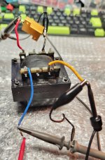
Ok -- Turned out one of my probes was bad. This time I also pulled the OPT entirely out of the chassi. See attached pictures for the setup and measured values.
Seems like it's flipped ~180 degrees, but I wasn't sure so I just measured it as is. There seems to be about 50 degree difference between 1k and 20k.
Going to give the triode strap a try, but i still haven't found any 470uF/400V caps to build the decoupling stage with. Sure you guys didn't mean 47uF? 🤔
Attachments


The motivation i need!We will get it up and running, and then you will have fun.
Do not give up.
Hey folks!
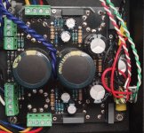
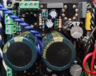
Recently bought myself a single ended E80CC/EL84 amp from a fellow enthusiast. First one I've ever had, and I primarily bought it to use with the Beta 8-loaded Dallas horns I'm building (Follow that bit here).
View attachment 1317576
To test the amp I hooked up some of my fathers' cheap logitech satellite speakers. Whatever was there sounded fine, and now knowing it worked I felt confident connecting the Beta 8's just for fun. After a minute or so, I noticed some low-frequency stuff happening and when I looked at the speaker cones they were oscillating something fierce. I cut power and proceeded to sweat bullets. Let it cool down and switched the tubes around, same thing happened. Went ahead and filmed it, oscillations visible only in the last few seconds.
I asked the guy I bought it off of if he'd ever had any issues of the sort, and he told me no. He'd only built it a few months back and had been running it for extended periods regularly through both his BR-mounted Flat 8's and some 3" Tang Band speakers. Upon request he provided the schematics for the amp -- Some sort of DIY kit he had bought off of Ebay. I'll be posting them below.
Only thing about the schematic that worries me is the absence of any kind of resistor on the screen grid, feel like you usually see those on pentode amps. That said, I'm still fairly new to valve amp design so any input from the sages here would be much appreciated.
In the meantime I'm going to borrow some 100x probes from work and feed it with my signal generator to see if I can make any sense of it. Have plenty of old radio drivers that I don't mind bricking for science.
Cheers,
J
Murphys Law of analog design:
If you want an amp, you get an oscillator. If you want an oscillator, you get an amp.
47uF sounds fine, I don't think I've ever seen 470uF caps used in this position in tube amps?Sure you guys didn't mean 47uF?
Yup -- just remembered the value wrong. Been rifling through my stash looking for 470uF/400V caps to no avail47uF sounds fine, I don't think I've ever seen 470uF caps used in this position in tube amps?

I have a few 10uF/400 caps, but not much else. Guess I'll just have to parallel a few!
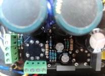
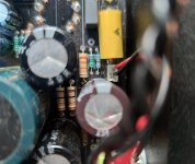
Could you read the labels on the grey caps and the yellow caps please. 10uF is good for now. What I don't understand is why its at 14Hz. The simulation does not predict this at all. That seems to suggest there's a mismatch of what's fitted against the schematic.
Grey/Black caps are 100uF/450V. Yellow caps are 1uF/250V.Could you read the labels on the grey caps and the yellow caps please. 10uF is good for now. What I don't understand is why its at 14Hz. The simulation does not predict this at all. That seems to suggest there's a mismatch of what's fitted against the schematic.
Misunderstood ya! Desoldered the coupling cap to EL84 and noticed it's .01uF! Way out of spec.Could you read the labels on the grey caps and the yellow caps please
Going to switch em over to 220 or 470, depending on what i have.
When I said grey caps I meant the coupling cap. That was the only thing that set off the oscillation in simulation. If I make it 10nf it goes off at 13Hz so an exact match. That's your problem - you better check all components.
Unreal. I was blind to it since they seemed appropriately sized -- always been one to miss the forest for the trees 
Took a good few hours, but I found two 220nF caps and 470nF caps each. Put the 470's as couplers and 220's for C1 and C7.
Going to put it all back together and give it a test, then see if i still run into oscillation issues @ higher loads.
If that's the case, interstage decoupling will be next in order, and then triode strapping.
I just noticed something that does not relate to your problems. But it should be changed anyway
Change the connection of R4:
Connect C2 to R3 (R4 does not belong between them).
Connect one end R4 to the newly connected junction of C2&R3
Connect the Other end of R4 directly to the socket tab of U1 g1 grid.
Done.
Now, when correctly connected, R4 acts as a grid stopper, which is its only reason for R4 to exist.
(the original connection of R4 is a very common mistake, both for the schematic, and for any such actual wiring connections).
Some people have stopped understanding the reason for, the theory behind, and the proper application of grid stoppers.
A. Sometimes, it can be helpful to run a simulation program, with the negative feedback Disabled:
Disconnect the 100 Ohm negative feedback resistor, R9 from the output transformer secondary (*), and connect that end of R9 to ground.
That will do 2 things:
1. Disable the global negative feedback.
2. Maintain the exact same bias voltage on the cathode of U2.
Now, re-run the simulation program, gain and phase, including the output transformer.
Is this a "New" Idea? . . . Special low frequency simulation to find the gain and phase?
B. Next, change the simulation schematic to put a 5k resistor across the output transformer primary, disconnect the 8 Ohm load from the secondary, and disconnect the global negative feedback as above (*).
Re-run the simulation program.
Since you know the primary inductance, no other details of the output transformers are needed in order to get a Very Accurate gain and phase at Low and Very Low frequencies.
This is key when adjusting low frequency time constants.
. . . Just another tool for your toolbox.
Many diyAudio fans have done A. above.
I bet very few have ever done a simulation as listed in B. above.
Comments, Please!
Last edited:
For my post # 60 above, here is some further explanation of why this idea works well at low frequencies:
Idea:
Change the simulation schematic: Connect 5k resistor across the output transformer primary, disconnect the 8 Ohm load from the secondary, and disconnect the global negative feedback.
Then . . .
When you run the simulation this way, this is the advantage at Low Frequencies:
The primary to secondary leakage inductance drops out of the equation.
The DCR of the secondary drops out of the equation.
The distributed capacitance of the primary drops out of the equation.
This technique can be helpful when you do not have any rating of primary to secondary leakage, no rating of the primary distributed capacitance, and no rating of the secondary DCR.
I almost forgot . . .
To make the simulation more accurate at Very Low Frequencies, Be sure to add a resistor in series with the primary inductance (a resistance that is the same as the primary DCR).
Thanks!
Have Fun!
- Home
- Amplifiers
- Tubes / Valves
- Oscillating/motorboating SE EL84 Amp