Also -- work didn't have any left over 100x probes, so I'll have to get one myself.
HOWEVER, I did notice when looking over the input transformer that some of the leads were in bad shape. I think the p/o had used some sort of glue to secure it to the enclosure, which deteriorated the sheathing. A few bare leads, some of which could very well have been shorts to ground. Two of them had fused together.
I repaired them and gave them some shrink tubing, so first matter of business tomorrow is to see if something was shorted. After that, a bit of measuring and some RC circuits on B+.
A g1 grid stopper, and a g2 grid stopper are used to prevent high frequency oscillation;
And sometimes a higher than normal resistance g2 grid stopper is also there to keep the screen from exceeding its dissipation limits.
Once a high frequency oscillation starts, sometimes that will act like a catalyst to also start a low frequency oscillation.
(Such as a low frequency instability that is not oscillating, but which can start once a high frequency oscillation starts).
Ah, gotcha -- Didn't know grid stopper was the general term, thought it only applied to the control grid.A g1 grid stopper, and a g2 grid stopper are used to prevent high frequency oscillation;
And sometimes a higher than normal resistance g2 grid stopper is also there to keep the screen from exceeding its dissipation limits.
Once a high frequency oscillation starts, sometimes that will act like a catalyst to also start a low frequency oscillation.
(Such as a low frequency instability that is not oscillating, but which can start once a high frequency oscillation starts).
I don't know the exact make, unfortunately -- They've been painted over. Only legible bit of information is "EI 73x28.3 SWU". First two parts I guess are that it's an EI core transformer, and the dimensions of said core. Measured it and they seem to be pretty close. Not sure what SWU means.If you send me the OPT you are using, I can take a look in simulation.
Other than that, I can only suppose it's a 5kprim/8ohm secondary transformer. Going to try measuring it with my component tester tonight.

- ==============================================================
- E80CC LTSpice model
- Modified Koren model (8 parameters): mean fit error 0.114556mA
- Traced by Wayne Clay on 05/24/2018 using Engauge Digigtizer and
- Curve Captor v0.9.1 from Philips data sheet
- ==============================================================
Bp P K I=
- (0.01823246698m)*uramp(V(P,K)*ln(1.0+(-0.1122041877)+exp((0.8506315156)+
- (0.8506315156)*((52.69367678)+(-3800.239263m)*V(G,K))*V(G,K)/sqrt((46.38864305)**2+
- (V(P,K)-(17.14739421))2)))/(0.8506315156))(1.240091528)
Cgk G K 3.1p ; 0.7p added (2.4p)
Cpk P K 0.65p ; 0.2p added (0.45p)
Rpk P K 1G ; to avoid floating nodes
d3 G K dx1
.model dx1 d(is=1n rs=2k cjo=1pf N=1.5 tt=1n)
.ends E80CC
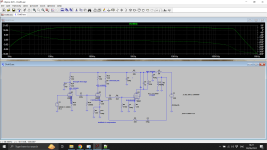
1) I tried 2n2 and 220R in series placed across the plate resistors R5 and R16. Very transformer dependent would need you to check.
2) Swap E80CC for 12AU7. Lowering the gain of the stages helps.
3) Decouple first stage. This helps with the LF stability.
4) Increasing coupling cap to EL84 220n->470n also helps with LF stability.
2) Swap E80CC for 12AU7. Lowering the gain of the stages helps.
3) Decouple first stage. This helps with the LF stability.
4) Increasing coupling cap to EL84 220n->470n also helps with LF stability.
Attachments

If you want to fix the LF end completely the FB compensation needs modifying. The components around the cathode interchange their positions. There an addition of a 470uF cap with the feedback resistor. This needs only to be 16V rated. Its quite a big change here. Hope this all helps.
I don't know why that 100uF always goes up to the cathode rather than down to ground. It only makes the LF lag worse. Probably copied from a 1960's mullard design and copied and copied. Placing it to ground allows the FB gain to increase on roll-off giving some lead compensation. Maybe somebody knows. Normally the FB is taken to the first stage and the FB resistor is in the kohms. This means the bias can share the FB resistor and the extra 470uF cap is not needed.
I don't know why that 100uF always goes up to the cathode rather than down to ground. It only makes the LF lag worse. Probably copied from a 1960's mullard design and copied and copied. Placing it to ground allows the FB gain to increase on roll-off giving some lead compensation. Maybe somebody knows. Normally the FB is taken to the first stage and the FB resistor is in the kohms. This means the bias can share the FB resistor and the extra 470uF cap is not needed.
Attachments
Last edited:
Component tester didn't tell me much, unfortunately. Only measured DCR, and inductance was ~26H. Forgot to measure parasitic capacitance though -- could calculate ACR using an equivalent circuit.Super putting simulation together at the moment... If you can get the primary inductance at say 25-59Hz that would be great. I will assume its a mullard style 3-3 transformer.
Absolutely invaluable help! The people in this forum never cease to amaze me.If you want to fix the LF end completely the FB compensation needs modifying [...]
Didn't get much done yesterday, some work stuff came in the way. Managed to put the amp back together to prepare for testing tonight, though. No 100x probes, but can at least see if the fixes on the input transformer did anything.
That said, I'm definitely going to add some decoupling between stages as per your recommendations!
I guessed 25H! If you want to try changes.
1) Fit the input decoupling.
2) Try 12au7 rather than e80cc to lower gain.
3) The dominate pole will need fixing. If you can put a 1KHz square wave in (from signal gen not DAC which is band limited) and take photo of waveform in 8R dummy load, that would help. I understand not everybody has access to these things.
Euro21 model has error as you can see some of it came out in bold. I tried a 6ac7 which is a better fit for simulation.
baudouin0,
In Post # 30, you said:
"I don't know why that 100uF always goes up to the cathode rather than down to ground. It only makes the LF lag worse."
If you look at the schematics in Post # 27, and Post # 29, the 100uF to the cathode Leads. It does Not Lag.
ELI the ICE Man. I, current; leads E, voltage. Current into the cathode, before the voltage across the electrolytic changes .
Just for example, consider a capacitor across the global negative feedback resistor, R9.
I think that Lead compensation.
Anyway, this thread is a good one!
JMartell,
If you have a scope and a signal generator, you can test for the Phase Lag (time lag) from the primary to the secondary.
A 40k resistor in series with the signal generator is the same as a 6BQ5 Beam Power / EL84 Pentode plate impedance, rp.
Load the secondary with an 8 Ohm resistor.
Using two probes (compensate them on the scope calibrator to make their high frequency response the same); and measure across the primary, veruss the secondary (both probes and both channels on).
Use that phase difference at 20kHz to calculate the value of input to output time delay (us); and put that in the simulation software.
360 degres at 20kHz is 50us. For example, 10 degrees phase difference is 1.39us.
Have fun!
OK its easy to understand lead and lag compensation at HF. For LF you and I may have the terms reversed. So I explain this differently. The more coupling caps the worse the LF stability gets. The OPT is also like a coupling cap in this respect.
If you use the traditional cathode FB method then its like another coupling cap for the feedback so the open loop gain drops at LF and the phase margin gets worse. If you take the cap to ground and apply the FB directly to the cathode with a potential divider then at LF the feedback gain goes up cancelling some of the degradation (pole - zero) cancellation. Some people think poles and zeros swap between LPF and HPF. Poles remain in the same place. Zeros change on the transfer function.
I am using the term lead and lag incorrectly for LF.
Its quite hard to explain and I've done it badly.
If you can get the open loop gain to start to increase rather than decrease in one stage at LF you can improve stability by lead-lag compensation. This is equivalent to placing a cap across the FB resistor at HF. Perhaps we should call it lag-lead compensation for LF. Ha Ha.
Last edited:
baudouino,
I need to turn my analysis part of the brain on.
Please give me time to formulate a better response.
The driver tube's cathode impedance is: [1/Gm + ((1+u) x Plate load resistor)] Ohms.
In the original circuit, the 100uF is driving that cathode impedance.
I believe that in No Case does the Current going into that cathode impedance Lag the Voltage that comes from the global negative feedback voltage of the output transformer secondary. That means the voltage at the cathode, leads.
Yes, at low frequencies there is less negative feedback voltage going to the cathode. The reason is twofold, the lower primary impedance due to the primary inductance, and the higher capacitive reactance of the 100uF at low frequencies.
At Extremely low frequencies, the capacitive reactance of 100uf is much much greater than the resistance of R7, so negative feedback at those frequencies is only a function of the complex voltage divider of R9, R8, R7, and the cathode impedance.
At DC, there is no feedback voltage from the output transformer secondary, because no DC comes from a transformer. The voltage divider R9, R8, R7 and the cathode impedance work at DC, but no DC signal comes from the secondary.
A single ended output transformer, with the plate and 8 Ohm taps wired for in-phase at midrange frequency,
At low frequencies, it will have a Leading phase response due to primary inductance. 6 dB per octave.
At high frequencies, it will have Lagging phase response due to primary to secondary leakage inductance, and distributed capacitance of the primary.
Many are unaware that an output transformer has Lead phase, Equal phase, and Lag phase.
(Please do not broadcast this fact to solid state fans, they may get excited so that they have a heart attack, and you have to call for an Ambulance).
Yes, with 3 RC poles in series (coupling caps driving resistors), causes a lead voltage. When each of those leads = 60 degrees, we have 180 degrees of lead.
Apply the output of an amplifier with 3 RCs back to the amplifier input, and you may get a Phase Shift Oscillator.
Also known as an improperly compensated Williamson amplifier. The key is to make the frequencies of the 3 poles be at 3 different frequencies.
I hope the above is all correct and true.
Please, somebody check my work above. Thanks!
Last edited:
I would say make 1 pole dominate so it cuts in early, bringing the gain down to unity before other poles kick in. You want G*F to be nowhere near -1 for all frequencies, as this results in large closed loop gain = G / (1 + G*F). Pole zero compensation sort of works works by cancelling the 2 pole and moving it to a position out of the way between the dominant pole and what was the unity gain point.
The trouble is negative feedback does require an understanding of the maths, and does get neglected by the diy audio'ers which is why we see issues.
Solid state fans did away with OPT's and that's a good thing - cost, weight and size as well as phase shifts, saturation, coupling etc.
The trouble is negative feedback does require an understanding of the maths, and does get neglected by the diy audio'ers which is why we see issues.
Solid state fans did away with OPT's and that's a good thing - cost, weight and size as well as phase shifts, saturation, coupling etc.
Last edited:
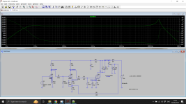
Ok, so -- yesterday I sat down and did some measuring with the picoscope. Inline resistor of 47k, the output impedance of the picoscope awg is ~600 ohms. Seems like the phase delay's sitting @ ~280 deg! Se picture below.

And today I put the amp back together and hooked it up with the signal generator. CH.A connected across the speaker leads. Noticed that the amp oscillated something fierce when I brought the volume pot above ~25%. Nominal amplitude @ 1kHz was ~30-50mV, and when it started oscillating it would spike up to almost 300mV.
I then turned the sig-gen off and saw that it was oscillating around 14Hz.

I'm far too new to amp design to draw any meaningful conclusions from this, and about 50% of the way to just taking the parts and building another amp.
Going to put in some 12AU7s' at least, and see if I can scrounge up some parts to add another decoupling stage!
And today I put the amp back together and hooked it up with the signal generator. CH.A connected across the speaker leads. Noticed that the amp oscillated something fierce when I brought the volume pot above ~25%. Nominal amplitude @ 1kHz was ~30-50mV, and when it started oscillating it would spike up to almost 300mV.
I then turned the sig-gen off and saw that it was oscillating around 14Hz.
I'm far too new to amp design to draw any meaningful conclusions from this, and about 50% of the way to just taking the parts and building another amp.
Going to put in some 12AU7s' at least, and see if I can scrounge up some parts to add another decoupling stage!
- Home
- Amplifiers
- Tubes / Valves
- Oscillating/motorboating SE EL84 Amp