No I'm not sure how to check that squarewave that went to ground.
Yes 505 is tied directly to the collector of q587
Yes 505 is tied directly to the collector of q587
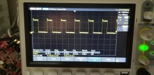
You set your scope so that the trace is on the reference line. Then you probe the output. Does the square wave go all of the way back down to the reference line every cycle?
How can the collector of the PNP driver not read less than 1 ohm to ground if it's directly connected to a point that's 0.2 ohms to ground?
You need to go back and re-check everything you used your meter for in this thread.
How can the collector of the PNP driver not read less than 1 ohm to ground if it's directly connected to a point that's 0.2 ohms to ground?
You need to go back and re-check everything you used your meter for in this thread.
Ok.
The lead had a burn in it. Yes my scope was set to the reference line. And it is reaching ground.
I now read to the pnp collectors .1ohm and to the c505 negative. And to the sg2535 pin 12 is .2ohms I was on the wrong pin I measured pin 13.
The lead had a burn in it. Yes my scope was set to the reference line. And it is reaching ground.
I now read to the pnp collectors .1ohm and to the c505 negative. And to the sg2535 pin 12 is .2ohms I was on the wrong pin I measured pin 13.
Last edited:
If the PNP collectors are grounded and the PNP transistors are OK, how can the base be swinging to ground while the emitter is not?
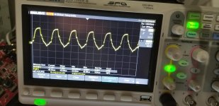
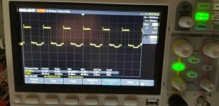
Set the trace to the reference line on the display, probe the output of the 3525, the base of the PNP drivers and the emitters of the PNP drivers. Are you still not getting a square wave that swings from ground to about 10v on the emitter of the drivers?
Set the trace to the reference line on the display, probe the output of the 3525, the base of the PNP drivers and the emitters of the PNP drivers. Are you still not getting a square wave that swings from ground to about 10v on the emitter of the drivers?
I have a sqaurewave at all three points it reaches ground. It changes if I insert a mosfet in the location. If I insert the new mosfet it in nstantly with heat up. With a mosfet in curcuit the drive then looks like a sawtooth.
That I don't know. The owner attempted a repair before I received it. I thought the same thing. Should I try a lower value?
In a similar amp, the 22.1 ohm is used. It could have been 27 ohm and the owner got the value wrong. I'd install a single 22 ohm in each bank and install an FET for each of those locations to see if it makes a difference.
When I reinstalled the rectifiers it goes into protection. I don't read anything shorted in the output section.
Some amps of similar design have a problem with open 10 ohm resistors connected to the emitters of the various voltage regulators clamped to the heatsink. I've been told they open due to leaky filter caps but I haven't seen that in the few I've repaired.
I don't see a 10ohmnresistor on this board anywhere. I pulled the outputs and tested them all. They are ok.
With no outputs in the amplifier. Recifiers installed the amplifier comes on and draws current and shuts off over and over. Are these the wrong rectifiers?
The silkscreen layout has the symbols for the rectifiers. Do they match what's printed on the face of the rectifiers?
- Status
- Not open for further replies.
- Home
- General Interest
- Car Audio
- Orion xtr2500.1Dz power supply