Hi there.
I have been given an Orion NT200 to try and repair.
It has been with another repairer who sadly couldn't fix it.
The fault is restricted to one channel only.
Confirmed by pulling the internal fuse for that channel.
The fault is, when powered up on the bench (no signal or speakers connected), the current draw will start climbing (1,2,3,4,5 amps) within a few seconds and the transformer for that channel will start whining louder and louder.
I disconnect the remote after those few seconds to avoid potential further damage.
So far all I have done is check the supply rails (~67volts dc)
I can see the previous work done to try and fix it.
Mostly re soldering, but q10/q29 and q16/q35 have been replaced.
q10 / q29 were mpsu07, now mje15030g
q16 / q35 were mpsu57, now mje15031g
Other than that as far as I can tell it appears all original.
Id love to attach the 2.6mg pdf, but the site won't let me.
If anyone needs this file (schematics and layout) please pm me with your email and I shall foward it on.
Its the same file that has been uploaded here -> orion_nt_series_schematics - Download - 4shared - Brad Walters
The diagram shows 50v caps. If that's what's in it and the rail voltage is going to 67v, the regulator may be defective.
Hi Perry.
Last night I realised I've made a mistake.
Been 20+ years since I worked on car audio.
The 67vdc I measured was across pos to neg, not gnd to pos / gnd to neg.
So best to disregard that voltage till I sit down and do some correct readings.
I've also worked out that;
The output transistors have been replaced on that channel.
And in my haste I didn't register that the other channel was drawing no current.
Where as I would expect to see maybe half amp.
So there could also be issues with that one.
Sorry for the goose chase.
When I get the chance I shall clear my head and get some proper readings.
Orion amps have a 10 ohm resistor between the collector of the PNP drivers and ground. Those commonly fail causing excessive current draw.
This gets better :|
Now that I've had a second to do a proper inspection.
Channel one is totally dead. No voltage generation at all from the power supply. No current draw.
Channel two is now (I don't know why) only drawing 1 amp. What I'd expect to see.
But its coil whine is still there.
Secondary voltage is +/- 34.75 well under the specified +/- 50vdc.
Looking at the schematic.
The one 494 is responsible for both power supplies.
I'm thinking that ic is shot.
One side dead.
And I'd bet without digging out the cro, the waveform on the other side will be up poo creek as well.
Looks like I'll have to replace the 494 before I can go further.
Who wants to place bets that's the entire issue ? 😀
Oh, and Perry, the 10 ohm resistors are fine.
The IC is only fed from one of the fuses. If you don't have that fuse in, the IC won't have supply voltage.
You should be able to pull Q75 and feed the collector pad to feed the 494 and then you should be able to check its function.
You should be able to pull Q75 and feed the collector pad to feed the 494 and then you should be able to check its function.
DOH. 😀
I did check ic voltages with the one fuse that seems to be for the 'whiny' channel.
That did give me the three 12v feeds into the ic.
Looks like i need to try with both fuses to make sure of what is or isnt working....
I did check ic voltages with the one fuse that seems to be for the 'whiny' channel.
That did give me the three 12v feeds into the ic.
Looks like i need to try with both fuses to make sure of what is or isnt working....
Right, so I lost that bet then didn't I.
With both fuses in, both supplies function.
Both produce about 34.5v per rail.
Second coil still whines.
Current draw starts at around 2.2amps.
After 10 seconds it rises to about 3amps.
Over the next 10 seconds it starts climbing until I power it down at 6 amps (and climbing).
Once it gets over 3amp draw the whine starts reducing until at about 4 amps its silent.
I measure under 15mv dc on the speaker outputs.
But I do measure ~1vac on the outputs, But thats just with a dmm so could be misleading.
Then again, The dmm (fluke) hasn't let me down yet.
It could be noise, but I'm not willing to 'sacrifice' a speaker just yet.
I've never seen an amp behave like this.
I can see why the previous repairer never succeeded.
Sadly I now need to put it aside while I catch up on other jobs.
Always the way......
EDIT.
The more I think about it, The more I wonder if it isn't a design/parts flaw.
Owner says he's always had issues with it overheating and shutting down.
Then someone told him "They are designed to be run without the bottom panel".
He removed the base plate and it seemed to be happy running like that.
Doesn't sound right to me.......
Last edited:
The PAM power supply produces far more heat than a PWM supply. In most of the amps using PAM, the power supply end of the heatsink heats up about as fast as the audio end. For PWM amps, the power supply end is generally much cooler than the audio end until the audio heat flows to the power supply end.
How did he mount it? If it was mounted on a flat surface, that would be the same as having the bottom cover in place.
Did you have the transistors clamped down tightly to the heatsink?
If so, measure the DC voltage across all of the emitter resistors. They should all read about the same and very near 0.000v DC (no signal, no load).
The regulated rail voltage should be about ±30v (looking at the regulator components on the diagram). Is that you you have?
I've never heard of PAM supplies before now.
I have no idea how it was mounted.
All I know is it's been at the last repairers for many months.
This gent has a really good reputation and apparently this is the only amp he failed to repair.
He's now retired.
I haven't touched the clamps at all so it should be ok.
Looking at it I think all work has been done from topside only.
As in cut legs, remove legs, solder in new parts.
All without the board being removed.
I shall check those voltages when I get the chance. But that could be a week away.
The rail voltages at the outputs are ~ +/- 34.5vdc.
So yup, that looks ok.
Right so finally back onto this amp.
When first powered up and not drawing over an amp;
Emitter resistors all have well under a 1mv across them.
Once it starts drawing current (I limit its potential draw to 4amps)
The em resistors on the side that hasn't been worked on are still below 1mv.
The em resistors on the side that shows signs of being worked on, well they ALL go up to 11mv.
Compare the voltage across the string of 6 biasing diodes on each channel as the amp begins to draw excessive current.
Across the entire string.
good channel 3.41v
bad channel 3.5v
And those voltages don't change at all irrespective of current draw.
good channel 3.41v
bad channel 3.5v
And those voltages don't change at all irrespective of current draw.
Try bypassing 1 or two of the biasing diodes to see if that makes a difference.
Have you confirmed that all of the transistors in the repaired channel are the correct for each location and installed with correct orientation?
Have you confirmed that all of the transistors in the repaired channel are the correct for each location and installed with correct orientation?
Perry, I very much appreciate the effort your going through to help me 🙂
Bypassing any single diode drops the voltage from 3.5v to 2.8v
Thats .7v so what I'd expect to see.
It also pushes the amp to full current draw and audible whine instantly.
I used a screwdriver blade to do the shorting, could be noise pickup through that.
Relevant info ? But I feel I should mention it.
Transistors, No, I haven't physically checked that.
At this time I am assuming the right parts are in the right spot due to the reputation of the previous tech.
Yes yes, I know, assumption is a very dangerous thing 😉
I haven't removed the clamps at this time.
And the legs on the :
q10/q29 and q16/q35 have been replaced.
q10 / q29 were mpsu07, now mje15030g
q16 / q35 were mpsu57, now mje15031g
Have been sleeved and 'twisted' around so again, I am assuming they are correct.
These have been swapped on both channels.
Since you mentioned it, I'm guessing you'd like me to pull the clamp and double check that area 🙂
I shall report back when I've done that.
I'd try using a jumper wire instead of the screwdriver, just to see if it acts differently.
If you have the long aluminum clamps, I'd suggest removing them as shown in the following graphic, if you have to remove them.
http://www.bcae1.com/temp/orionampclamps.swf
If you have the long aluminum clamps, I'd suggest removing them as shown in the following graphic, if you have to remove them.
http://www.bcae1.com/temp/orionampclamps.swf
I bought a faulty Maplin 50 watt amp off ebay.
Someone had tried to fix it but had given up as a couple of transistors were missing.
I replaced the missing transistors.
The amp sort of worked but was very distorted.
I checked every component on the pcb and they all DMM'ed OK.
I powered it up and found some strange voltages across one transistor.
So I DMM'ed the transistor again and realised someone had put in a pnp instead of an npn transistor. The transistor markings were worn off so were useless.
When someone else has had a go you can end up with all sorts of problems they added as well as the original fault.
I'd try using a jumper wire instead of the screwdriver, just to see if it acts differently.
If you have the long aluminum clamps, I'd suggest removing them as shown in the following graphic, if you have to remove them.
http://www.bcae1.com/temp/orionampclamps.swf
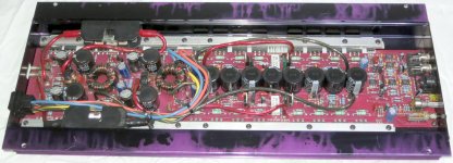
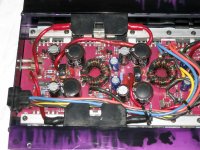
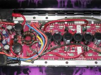
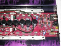
Hopefully this is helpful.
Tried to keep these as big as possible, also increased lighting in post process to help make it clearer.
EDIT, yup, that works, you can see the bits hes replaced/resoldered/etc.
Attachments
Last edited:
I bought a faulty Maplin 50 watt amp off ebay.
Someone had tried to fix it but had given up as a couple of transistors were missing.
I replaced the missing transistors.
The amp sort of worked but was very distorted.
I checked every component on the pcb and they all DMM'ed OK.
I powered it up and found some strange voltages across one transistor.
So I DMM'ed the transistor again and realised someone had put in a pnp instead of an npn transistor. The transistor markings were worn off so were useless.
When someone else has had a go you can end up with all sorts of problems they added as well as the original fault.
Yes. I don't normally trust others work, but I know this guys reputation.
But just to make sure, I shall pull the clamp and double check.
- Status
- Not open for further replies.
- Home
- General Interest
- Car Audio
- Orion NT200 fault finding help