Perry Babin said:With the resistor out of the circuit, do you still have the following voltages on the pins of the opa134?
Pin 1:.12.8
Pin 2:.1.4
Pin 3:.13.1
Pin 4:.-13.2
Pin 5:.0
Pin 6:.12.1
Pin 7:.13.2
Pin 8:.12.8
Does one end of the resistor you pulled go directly to pin 3 of the 134?
On the channel w/ pulled resistor-
Also did you read up above about the tl494?
Pin 1: -08.1
Pin 2: -07.2
Pin 3: -08.1
Pin 4: -13.5
Pin 5: .0
Pin 6: -13.1
Pin 7: 13.2
Pin 8: -08.1
and yes it goes to pin 3.
I don't think it has anything to do with the work near the 494 but I wouldn't rule anything out at this point.
Connect pin 3 of the 134 to the secondary ground. It will be easy to do on the bottom of the board. The secondary center tap is connected to the rail caps near the 134 by two wide traces. Confirm that you have the correct trace by checking for continuity between the secondary ground on the rail capacitor and the non-bridging speaker wires (no power applied to amp). You should read ~0 ohms.
With pin 3 connected to the secondary ground, do you still have 30v on that channel?
Perry Babin said:I don't think it has anything to do with the work near the 494 but I wouldn't rule anything out at this point.
Connect pin 3 of the 134 to the secondary ground. It will be easy to do on the bottom of the board. The secondary center tap is connected to the rail caps near the 134 by two wide traces. Confirm that you have the correct trace by checking for continuity between the secondary ground on the rail capacitor and the non-bridging speaker wires (no power applied to amp). You should read ~0 ohms.
With pin 3 connected to the secondary ground, do you still have 30v on that channel?
No Voltage.... in fact it reads -.007 when turned on. So what does this mean?
It appears that you probably have an open ground in the circuit.
On the bottom of the board near the muting transistors, two of the resistors go to the large secondary center tap trace via a couple of small traces, are the small traces open (look closely).
If not, there is a resistor that goes from one end of the resistor you pulled to that same small secondary ground trace. Is that resistor open in either channel (pull one end to measure resistance)?
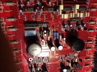
If neither of these are open, you will need to send me a photo with the all of the top traces in the area highlighted (like you did before in white) but I need it at full resolution. You'll need to do this on the channel with Q19 because I can't see the bottom traces in the other channel (regulators in the way). If you've been working in the other channel, you can continue in that channel but you'd need to send me another photo with the regulator transistor pulled out of the way and the adhesive cleaned from the board.
On the bottom of the board near the muting transistors, two of the resistors go to the large secondary center tap trace via a couple of small traces, are the small traces open (look closely).
If not, there is a resistor that goes from one end of the resistor you pulled to that same small secondary ground trace. Is that resistor open in either channel (pull one end to measure resistance)?
If neither of these are open, you will need to send me a photo with the all of the top traces in the area highlighted (like you did before in white) but I need it at full resolution. You'll need to do this on the channel with Q19 because I can't see the bottom traces in the other channel (regulators in the way). If you've been working in the other channel, you can continue in that channel but you'd need to send me another photo with the regulator transistor pulled out of the way and the adhesive cleaned from the board.
hello to all! I'm new on this forum ... my name is Antonio from Italy, I have a problem with Orion HCCA 275 G4
* there is someone that I can 'say the exact locations of the 3 J.FET 2n5639?
thank you!
* there is someone that I can 'say the exact locations of the 3 J.FET 2n5639?
thank you!
Hello, Had the this Orion up and going at one point a few years back and installed it to a subwoofer, it worked great for a day or two before it started leaking dc voltage and almost ruined the woofer. So I pulled it and was going to send it to Perry but never got around to it. So I pulled it out of the closet last week and hooked it up on the bench to test, It is working fine now😱. So not sure what is going on? I did notice these 2 resistors that immediately get hot as soon as the amp is powered. I think they are between the power supply and preamp. This is my question, should they get this hot this quick?
Attachments

In two other amps like this, the value is 180 ohms. They are likely to operate at high temperatures.
In two other amps like this, the value is 180 ohms. They are likely to operate at high temperatures.
Ok, these are" 68 ohm 5% 2 watt " resistors. So you think it should be pretty normal for them to stay really hot?
When I first kicked it on they smoked the dust off of them and smelled pretty hot.
Also, since this amp is a little flaky, Is there anything I can do to protect the speakers when installing this amp back into the vehicle? like add or remove something in the preamp section to protect against this happening again? I just don't know if it is an op-amp oscillating or a bad ground somewhere?
Last edited:
They use large resistors because they are required to dissipate a lot of power (in the form of heat). I don't know what is normal but as long as they're not dissipating more power than they're rated for, it could be normal.
You can use the formula P=V^2/R to determine the power dissipation. I don't know how useful it will be with the 68 ohm resistors. I'm assuming that they're not the original parts since other amps of the same model used 180 ohm resistors.
You can use the formula P=V^2/R to determine the power dissipation. I don't know how useful it will be with the 68 ohm resistors. I'm assuming that they're not the original parts since other amps of the same model used 180 ohm resistors.
Now that I look close they do look like they have been pulled or replaced. Why would someone install a totally different value resistor? what do these resistors do in the circuit?
I think they drop voltage going to the regulator transistors.
Do the resistors connect to the center leg or the first leg of the regulator transistors (the ones on the wires)?
They may have been burned beyond recognition.
Do the resistors connect to the center leg or the first leg of the regulator transistors (the ones on the wires)?
They may have been burned beyond recognition.
They are used to drop some of the voltage which means that less power is dissipated by the transistors. As long as the voltage getting to the collectors of the regulator transistors is sufficient to allow the regulated to remain regulated, the resistor value isn't all that important. The regulator transistors are generally clamped to the heatsink so they can dissipate significant power without overheating.
If the resistors run extremely hot, I'd suggest installing them with long leads so that they cannot transfer the heat to the board (which will get damaged and may become conductive).
If the resistors run extremely hot, I'd suggest installing them with long leads so that they cannot transfer the heat to the board (which will get damaged and may become conductive).
Ok, Since I will probably take your advice and go with longer leads, should I go back to the 180 ohm resister?
What kind of problems do you typically find with this model amp when it comes to stray voltage leaking?
What kind of problems do you typically find with this model amp when it comes to stray voltage leaking?
The most common (strange) problem I've seen with this type of amp is open shield grounds between the RCA jacks and the rest of the amp.
The op-amps in the output stage are responsible for the elimination of the DC offset.
If you have to replace them (for longer leads), I'd suggest going back to the 180 ohm but I'd also suggest ordering new 68 ohm (what's in it now) in case they were replaced for a valid reason.
The op-amps in the output stage are responsible for the elimination of the DC offset.
If you have to replace them (for longer leads), I'd suggest going back to the 180 ohm but I'd also suggest ordering new 68 ohm (what's in it now) in case they were replaced for a valid reason.
I remember this amp had that problem too "Open ground to rca shields". I remember when I tried to ground them, a couple of traces on the bottom of motherboard started smoking. but I don't remember if when I replaced the opa134's or the transistors next to them solved that problem.
Which op amps are the output stage? I think there is 4-quad amp op amps and 2-single amp op amps, correct?
Which op amps are the output stage? I think there is 4-quad amp op amps and 2-single amp op amps, correct?
The 134Ps are the op-amps for each channel's drive circuit.
For one channel, post the DC voltage on all pins of the 134 and the DC voltage measured directly across the speaker terminals for that channel. When measuring the DC voltage on the op-amp, place the black meter probe on the non-bridging speaker terminal for that channel.
Do you have continuity between the non-bridging speaker terminal and the RCA shield?
OK, While testing voltages on opa134's the right speaker popped and pulled in with no input on rca's.
1. 4.4
2. 0
3. 0
4. -5
5. 4.4
6. 4.7
7. 1.0
8. 0
These voltages were read with Black probe on Right speaker terminal neg. channel (Non Bridging) Looks like I still have a problem.
I get 00.2 between Right neg speaker terminal and Right rca shield.
1. 4.4
2. 0
3. 0
4. -5
5. 4.4
6. 4.7
7. 1.0
8. 0
These voltages were read with Black probe on Right speaker terminal neg. channel (Non Bridging) Looks like I still have a problem.
I get 00.2 between Right neg speaker terminal and Right rca shield.
Last edited:
- Status
- Not open for further replies.
- Home
- General Interest
- Car Audio
- Orion HCCA 275G4