This amp is kicking my butt. When I got the amp I replaced a bank of NDP7060's only 4 of them were bad but I replaced all 6. Also replaced the TL494CN, It looked like it had been hot along with 2- 47uf 25volt and 1- 1uf 50volt caps next to the TL494CN. I then installed 1- 5 amp fuse on the left channel and one on the right channel. Powered it up and was getting loud humming on both channels, like when the RCA's aren't grounded. Music wasn't loud either. Then the fuse went. checked all the NDP7060's and found one bad that I installed. Replaced it. Replaced fuse and powered on again. Then 2- 2N5639's OP amp's popped. So I then noticed that when handleing the cicuit board I had smashed some other op amps over and they were shorting on some nearby resistor's in the preamp section. Which is why I was getting the humming noise in the speakers. So I made repairs and replaced the 2- 2N5639's and powered up again. No humming this time but only stayed on for 10 seconds and blew the right channel fuse. This amp has 3 - 30 amp fuse's per channel. 180amps total, So I tried a 10amp on right channel and it stayed on alittle longer but the speaker made like a melting noise before it blew the R. channel fuse again. I don't know where to go from here. PLEASE HELP ME...
Attachments

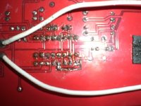
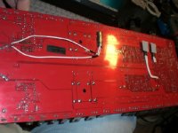
Also in the pic above with the TL494 the multi resistor I accidently removed thinking it was one side of the TL494 and it got pretty hot, Would that hurt it? Also on the bottom of that resistor somebody ran a jumper from one leg to another. I don't think this amp had ever been opened before so maybe it was a design flaw and the factory jumpered it? Here is a picture of the bottom.
Attachments

jol50 said:What is the voltage on the speaker terminals?
With music or no music?
The 2N5639 is a jfet. It's used in the muting circuit.
http://www.onsemi.com/pub/Collateral/2N5638-D.PDF
If one channel is blowing fuses, you need to isolate the problem. If you have a 2 ohm resistor, it will make it easier. Running through the resistor, you can measure the voltage across the emitter resistors in the audio section. If the voltage across any resistor is more than ~0mv, you need to determine why. Compare the voltage across the emitter resistors on the good channel to those on the bad channel.
Be careful. Even though you're using a resistor to limit current, it doesn't mean that it will prevent damage. Have all components clamped to the sink to help insure that nothing will be damaged.
If there is absolutely no voltage across the emitter resistors on either side, the problem is likely in the power supply. If half of the FETs in the defective channel are getting hot, the problem is probably in the drive circuit. Remember that these Orion amps often blow the driver transistors and the 10 ohm collector resistor of the PNP driver transistors.
For the 1% components, the resistor color code for the 10 ohm resistor is brown, black, black, gold, brown. One end of the resistor will go to the third leg of the MPSA56. The other end will go to ground.
Itsme said:
With music or no music?
With nothing but power hooked to amp, but what Perry said will show even more. Should do that with it unhooked and idle too. Watch out for hot things, if sink gets hot at a chip(s) shut it off and let it cool and start testing again. Or if you smell or feel heat/etc. The resistor helps cut the power supply and fuses might save parts. Man that is a big amp.
Checking the output resistors will tell if you have some kind of feedback/etc that is running current through the outputs that should not be. Nothing hooked up to amp=no music out=0 current in outputs or very close to 0. If no current then like he said you know it is likely a power supply problem.
I haven't tested yet, just after reading your responses I went and checked my 8 ohm bookshelf speaker I use to test my amps with and now it is a 0.1 ohm speaker.🙁
So apparently I am getting alot of voltage through my speaker outputs.
I will test like you said, But what if it keeps blowing the fuse before I can test? Is there any testing I can do without powering up first? thanks.
So apparently I am getting alot of voltage through my speaker outputs.
I will test like you said, But what if it keeps blowing the fuse before I can test? Is there any testing I can do without powering up first? thanks.
You should always have capacitors in series with test speakers. 100uf 100v non-polarized are a good choice.
You can easily check the power supply driver transistors and resistors.
Do you know if the speaker was damaged before you repaired the amp or after you replaced tha parts?
If it's blowing fuses, it's unlikely that it could produce enough voltage to damage the speaker even if there was a problem in the audio section.
If the rectifiers are easy to remove, pulling them from the defective channel will isolate the audio section from the power supply section. If the fuse blows without the rectifiers, you have power supply fault. It coud be defective driver components or possibly a shorted transformer.
It almost sounds like some kind of preamp circuit issue or something just before the output fets causing them to oscillate or latch...? Wow, that amp has the potential to be a financial disaster under the right conditions, so many fets
In your second picture it almost looks like one of the legs on the bottom row (5th) seems to have a spot where its actually connected to the large trace at the bottom area. Look at the small silver jumper about in the middle, almost looks like a small spot where it bonded to the lower area. Are they supposed to be seperate?
sorry for my crappy edit skills:😱
An externally hosted image should be here but it was not working when we last tested it.
Perry Babin said:You should always have capacitors in series with test speakers. 100uf 100v non-polarized are a good choice.
You can easily check the power supply driver transistors and resistors.
Do you know if the speaker was damaged before you repaired the amp or after you replaced tha parts?
If it's blowing fuses, it's unlikely that it could produce enough voltage to damage the speaker even if there was a problem in the audio section..
Ok.. I have 29.7 volts DC on both left and right channels. I didn't have good connection to other speaker apparently and that is why it didn't blow fuse on that channel.
And yes, the speaker was good. Heard it play hour before testing.
So what should I do now??? Also nothing got hot.
PPIa600: No that was a repair trace ontop of old trace, after looking at it closer. Thanks anyway.
Oh, Something strange though was I got -000 when test voltage across channel bridging speaker output terminals. Even when reversing the probes - + set at 200 volt DC range on meter.
Do you have both plus and minus rail on the output transistors?
Plus and minus 15v reg on the op-amps?
Power supply voltage on pins 11 and 14 of the digital level IC (DG405?)? I don't know if this IC runs off of 5v rails or 15v rails.
If the output voltage was exactly the same on both bridged outputs, the meter would have read 0v when the leads were placed across them.
Perry Babin said:Do you have both plus and minus rail on the output transistors?
Plus and minus 15v reg on the op-amps?
Power supply voltage on pins 11 and 14 of the digital level IC (DG405?)? I don't know if this IC runs off of 5v rails or 15v rails.
If the output voltage was exactly the same on both bridged outputs, the meter would have read 0v when the leads were placed across them.
I'm sorry Perry, I don't understand the 1st 2 questions. And how do they number the pins on DG405
😕
For virtually every amplifier, you have both positive and negative voltage for the audio section. The output transistors operate off of the main rail voltage which is typically plus/minus (±) 35 volts but can be higher or lower depending on the amp.
The preamp section typically operates off of ±15v (plus/minus 15 volts). This should be present on all of the op-amps in the audio section.
For the pin configuration, look up the datasheets for each of the components. The 8 pin op-amps will all have the same pin configuration. All of the 14 pin op-amps will have the same pin configuration.
14 pin op-amp:
http://www.national.com/ds.cgi/LM/LM837.pdf
8 pin op-amp:
http://semicon.njr.co.jp/njr/hp/fileDownloadMedia.do?_mediaId=150
Digital pot:
http://datasheets.maxim-ic.com/en/ds/DS1267.pdf
CMOS switch (not a digital pot):
http://www.ortodoxism.ro/datasheets/vishay/70049.pdf
Perry Babin said:Do you have both plus and minus rail on the output transistors?
Plus and minus 15v reg on the op-amps?
Power supply voltage on pins 11 and 14 of the digital level IC (DG405?)? I don't know if this IC runs off of 5v rails or 15v rails.
If the output voltage was exactly the same on both bridged outputs, the meter would have read 0v when the leads were placed across them.
ok Perry, I have 27 volts between pin 11 & 14 on the DG405 and I am getting from B+ to outside legs of output transistors 41 volts on some and 29 on others and the only thing getting hot is the Century - CEN-0U7's 4 on each channel.
Are you also getting -41 and -29 on half of the outputs?
What are the part numbers on the output transistors?
In this amp, for each channel, are the center legs of all of the outputs connected (0 ohms between them) or are all of the right-most legs connected (0 ohms between them)?
The central transistors will probably run warm.
Do you also have plus/minus voltage on all of the op-amps?
Perry Babin said:Are you also getting -41 and -29 on half of the outputs?
What are the part numbers on the output transistors?
In this amp, for each channel, are the center legs of all of the outputs connected (0 ohms between them) or are all of the right-most legs connected (0 ohms between them)?
The central transistors will probably run warm.
Do you also have plus/minus voltage on all of the op-amps?
Ok on the output's- there is 6- 2SD1047E's per channel that I am getting 43 volts on outside legs & -16 volts on middle leg from B+ terminal the other 6-2SB817E's in the channel I am getting -16.5 on left & middle legs & -17.4 on the right leg.
OP amps:
OPA134PA's - V- = -13.63 & V+ = 12.94
LF444CN & LM837N I got the same voltages as above.
And yes the middle legs are 0 ohm's on the output's
On the 2SB817E's, are the 1st and second legs shorted together? If they seem to be shorted, the drivers may be shorted.
Why are you measuring the voltage from B+? Use the secondary center tap of the power transformer when measuring voltage in the audio section.
Why are you measuring the voltage from B+? Use the secondary center tap of the power transformer when measuring voltage in the audio section.
- Status
- Not open for further replies.
- Home
- General Interest
- Car Audio
- Orion HCCA 275G4