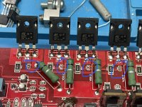
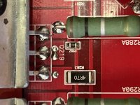
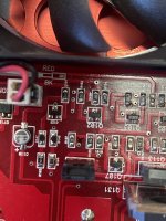
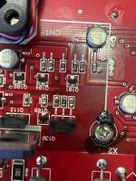
So I replaced the blown bond resistor, noticed the FETs were mismatched from a previous repair (stickler for my gear running as prime as possible) so decided to swap out all the output FETs (TIP35c/36c) from the lesser version to the better ST, matched set, and just got done looking over my joints (haven’t even cleaned flux off the board yet) and noticed this amp is either missing 2 resistors in the TIP35C section on each half or empty but mismatched areas from factory? I tested amp after bond resistor replacement before FET change out and it seemed to run great at idle, so I’m guessing this was in purpose from factory? Why are they not in same exact area on each side? Did the previous tech who repaired the first blowout using mismatched batch/brand FETs remove them? Each resistor is 22 Ω and even the empty resistor sockets probe are 22 Ω as well.
Just trying to make sure the amp is running proper, and this just doesn’t look right, if it was from factory I’d expect it to look the same on both halves of the board, any info/insight would be greatly appreciated. Resistors of concern/empty sockets circled in blue.
Also depending on answer, can I move the one resistor that isn’t on one of the 2 outside FETs to the outside to match the other half of board? Just OCD preference, lol, just looks as if location doesnt matter just as long as 2 are there like it looks, placement looks random 😅 unless there is 2 from each side in fact missing 🙃 or would it be better to have the resistors as populated/unpopulated/populated/unpopulated or like I 1st mention as populated/unpopulated/unpopulated/populated …I know this may be overthinking but still would like to know 🤓
Thanks guys 🖖🏼
Attachments
Last edited:
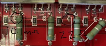
Each resistor is marked 220 and you read 22 ohms across every pair of pads for each of those 4 resistor locations?
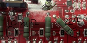
After you asked I went back and actually checked, I just assumed they were all 22 Ω since the 2 resistors that were in different spots read “220” on the resistor and all 4 resistor locations (wether populated or not) read as 22 Ω but the first resistor on each half of the board is actually a 10.1m Ω “1015” …I should have made sure by checking each instead of assuming 🤦🏼 But that makes this even weirder, but I’m not the best at A/B so 😅
Attachments
I also just probed my channels and the channels that was previously repaired has over -400mv of dc offset, other channel has 5mv. I doubt that has anything to do with these but wanted to note it, another topic maybe to correcting that?
Are all of the emitter resistors within tolerance?
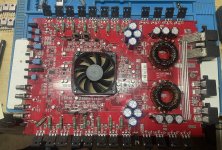
The DC offset is generally controlled in the differential circuit which is likely near the fan on this amp.
In this amp, is the rail voltage on the collectors or on the emitters of the output transistors?
The DC offset is generally controlled in the differential circuit which is likely near the fan on this amp.
In this amp, is the rail voltage on the collectors or on the emitters of the output transistors?
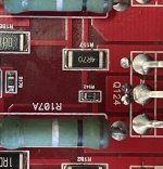
Yes, all emitter resistors are spot on .1 Ω
Rail voltage, 60v, is on the collectors
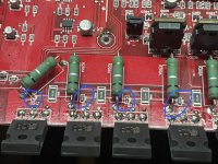
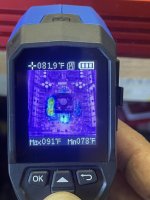
And I think I might have found my problem, my newest addition to the toolkit, and already loving it, thermal imaging camera with picture overlay 🤓 Seems my b631k/d600k are out of spec? Which I can’t seem to find anywhere but eBay 🤦🏼 Searched Mouser&Digikey for KTB631k/2sB631k and coming up empty handed. Is there another model number to search for for these components and their complements? What is usually considered the best brand for these? I need a new set for my HCCA 2000.4 I just got as well 🙂
I’m going retake some thermal pics and get in close with my thermal to make sure, going to probe each component in that area as well to make sure all within spec. 99.999% sure the dc offset problem is in this area 🤙🏻
Rail voltage, 60v, is on the collectors
And I think I might have found my problem, my newest addition to the toolkit, and already loving it, thermal imaging camera with picture overlay 🤓 Seems my b631k/d600k are out of spec? Which I can’t seem to find anywhere but eBay 🤦🏼 Searched Mouser&Digikey for KTB631k/2sB631k and coming up empty handed. Is there another model number to search for for these components and their complements? What is usually considered the best brand for these? I need a new set for my HCCA 2000.4 I just got as well 🙂
I’m going retake some thermal pics and get in close with my thermal to make sure, going to probe each component in that area as well to make sure all within spec. 99.999% sure the dc offset problem is in this area 🤙🏻
Attachments
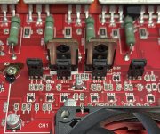
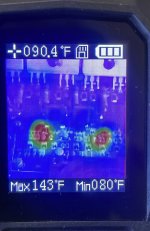
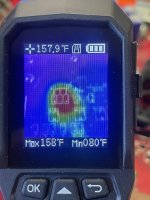
I marked on the board where the heat was concentrated on each side with an X, each of the resistors are within spec on both sides, would the actual component they are in front of be offspec and cause this?
Attachments
Do those resistors in the other channel run cool?
Are they the same value in the other channel?
Do both channels produce clean audio up to clipping with a speaker/dummy load?
Are they the same value in the other channel?
Do both channels produce clean audio up to clipping with a speaker/dummy load?
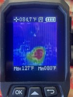
I stepped away from my bench but I’ll check on the values to see if they match (should have done that already) and I don’t have a way to test up to clipping yet, still working on that (waiting for cells now for in-house bank) but the thermal shows that’s really only the thing heating up and it’s fright from boot up, nothing else @ idle even gets warm
Attachments
Will do, I have cells that will be here soon, plans to build an in-house lithium bank fed by my 100amp power supply for proper high current testing, going with Spim08HP, I use it in my vehicle and am loving it. I’ll report back once I have 🤙🏻
- Home
- General Interest
- Car Audio
- Orion HCCA 1200.2 OutPut resistor question