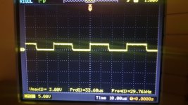

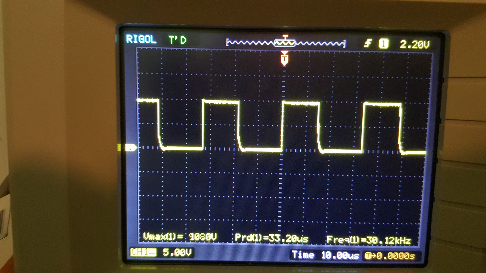
For the right image, there is a problem. Confirm that you read 10 ohms from the collector of the PNP driver transistors to ground.
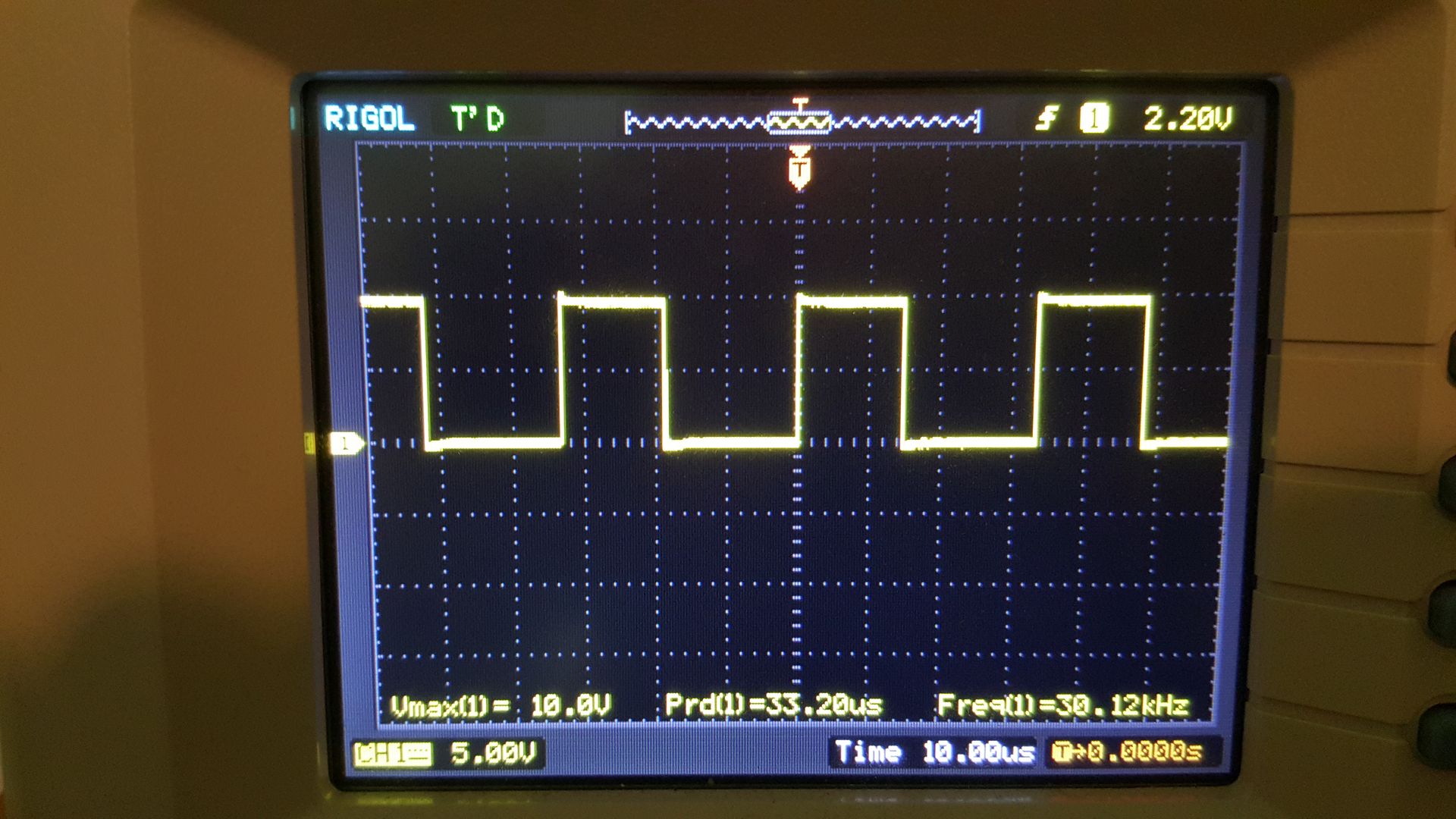
There may be another problem as well. With no rail voltage, I'd expect the amplitude to be greater on the left image but that's something to troubleshoot later.
There may be another problem as well. With no rail voltage, I'd expect the amplitude to be greater on the left image but that's something to troubleshoot later.
For the right image, there is a problem. Confirm that you read 10 ohms from the collector of the PNP driver transistors to ground.
There may be another problem as well. With no rail voltage, I'd expect the amplitude to be greater on the left image but that's something to troubleshoot later.
I get 9.7 ohms between the Q18 collector and ground.
Last edited:
I think so Perry as the driver side of the gate resistors had continuity with the emitter junction of q17 and q18.
Last edited:
Follow the two circuits from pins 9 and 10 to the two sets of drivers. Find the break between 9/10 and the drivers with no signal on their bases.
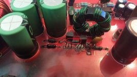
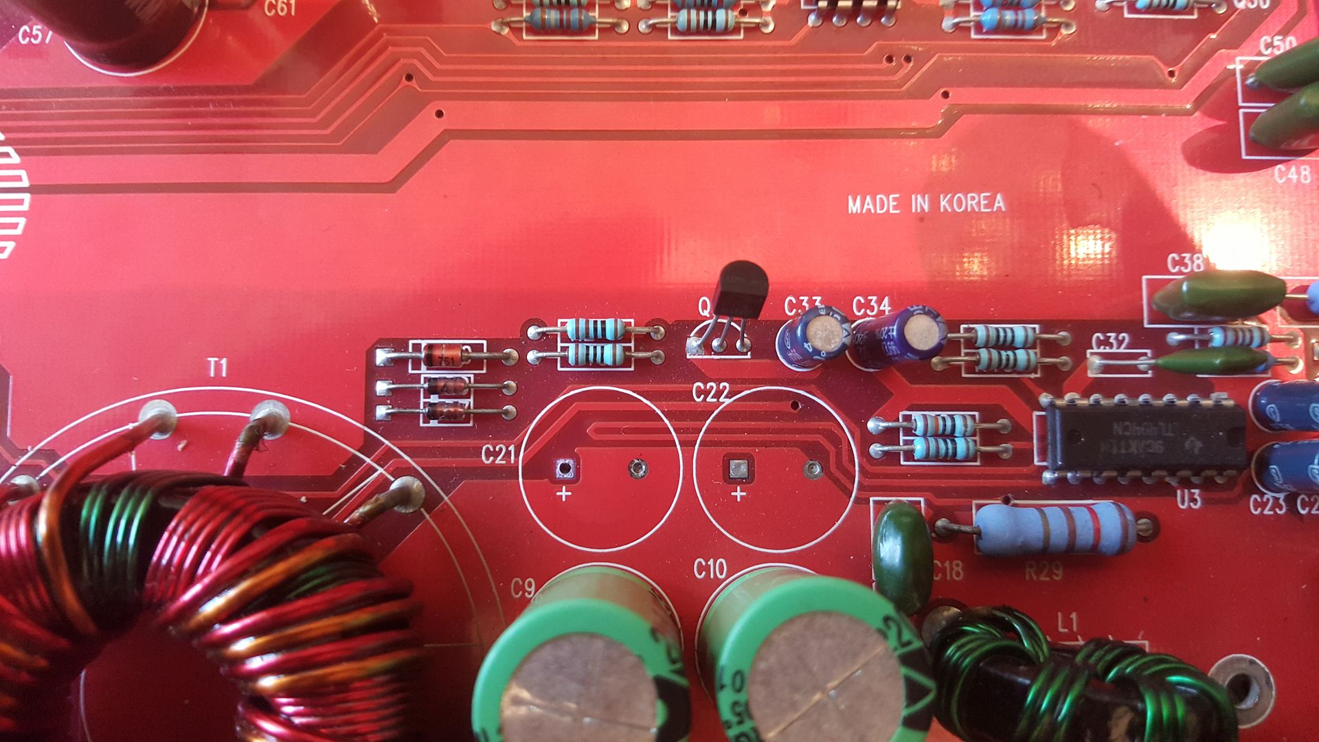
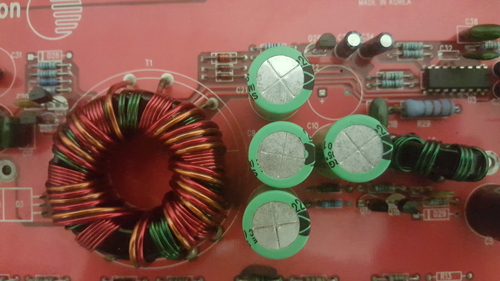
Heres the culprit Perry,
Left photo R22 110 ohm 5% wide open 😱
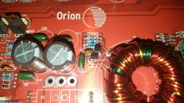
Who would think it would be this one that broke when you look at the ones around it. The one that looks burnt out is good. It leads to the other npn/pnp junction is sitting at 10 oclock of the inductor in the right photo.
Hugh
Left photo R22 110 ohm 5% wide open 😱
Who would think it would be this one that broke when you look at the ones around it. The one that looks burnt out is good. It leads to the other npn/pnp junction is sitting at 10 oclock of the inductor in the right photo.
Hugh
Attachments
Last edited:
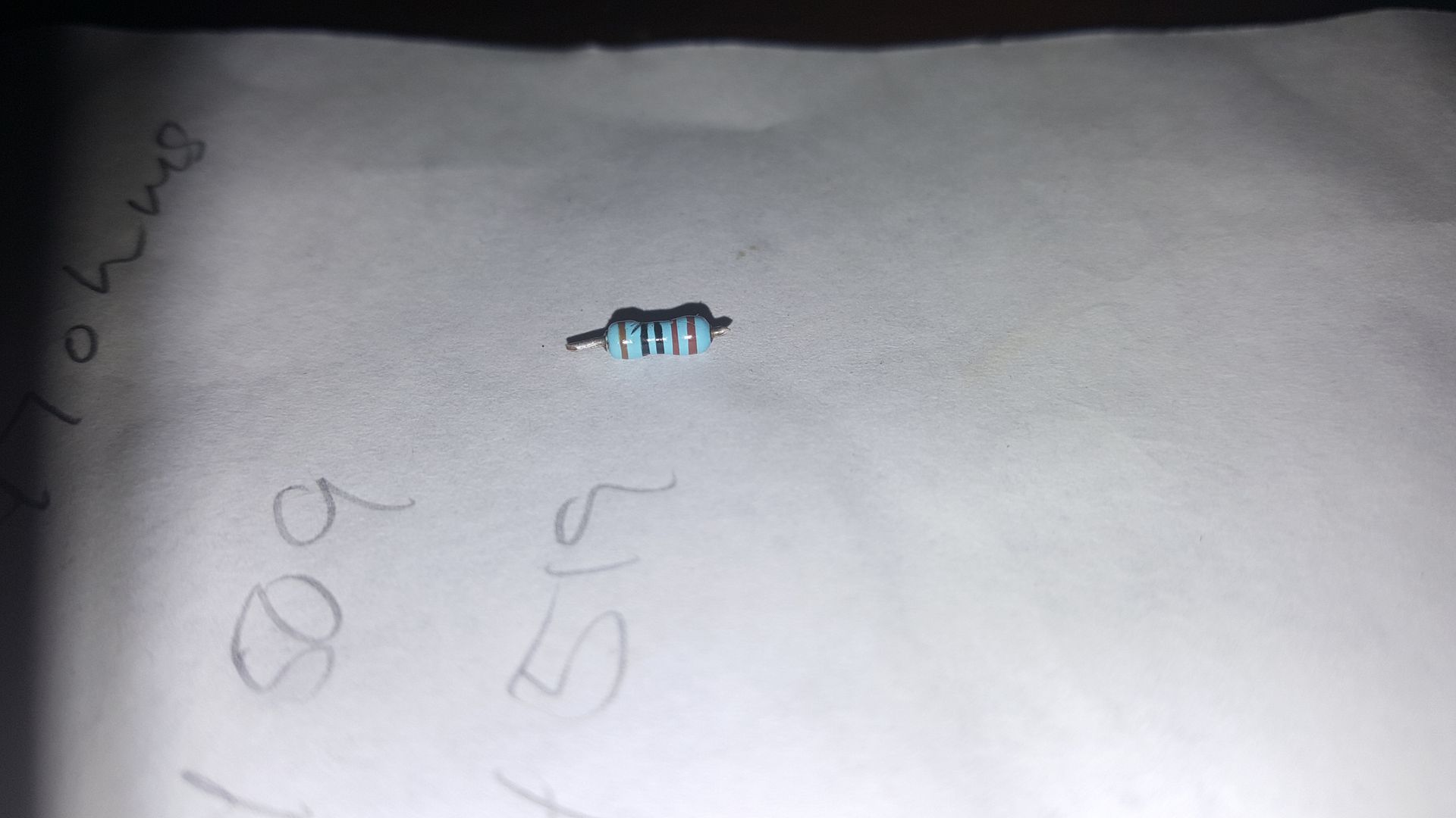
My kids 13 and 9 assured me this was brown, brown, black, black, gold. Heres the thing with the meter. No continuity through it but measures 1k on auto. If it was brown black black brown brown it would be 1k at 1%. What do you think? one thing is for sure pin 9 has continuity all the way to the circuit by the inductor pin 10 stops dead in it tracks across this resistor. om the other side of it in too has continuity all the way to the circuit at 10 oclock of the inductor.
Last edited:
Is there a corresponding resistor for the other drive circuit?
Go to walmart and boy one of the following otoscopes ($18). They're near the pharmacy. Perfect lighting and very good lens. The lens scratches easily but if you take care of it, it's OK.
Otoscope, Otoscopes
Go to walmart and boy one of the following otoscopes ($18). They're near the pharmacy. Perfect lighting and very good lens. The lens scratches easily but if you take care of it, it's OK.
Otoscope, Otoscopes
Hi Perry,
All the other resistors bearing the same color bands measure 1k and likewise wont trigger continuity on the multimeter across them . So is it possible I have a problem with q17,q18 if there is continuity between the left leg of r22 and the other driver circuitry and between the right leg of r22 and pin 10 and the resistor is functioning as it should? Im a bit stumped. the q17, q18 junction is responsible for driving the signal seen at the gate resistors scope photo on the right in post #41. You dont think theres a possibility these transistor are still a problem?
All the other resistors bearing the same color bands measure 1k and likewise wont trigger continuity on the multimeter across them . So is it possible I have a problem with q17,q18 if there is continuity between the left leg of r22 and the other driver circuitry and between the right leg of r22 and pin 10 and the resistor is functioning as it should? Im a bit stumped. the q17, q18 junction is responsible for driving the signal seen at the gate resistors scope photo on the right in post #41. You dont think theres a possibility these transistor are still a problem?
Last edited:
The term 'continuity' is vague and generally best avoided.
You should be able to see two identical circuits. They should behave in the same way. The readings should be the same. If you cannot see where the fault is, draw a diagram with the components labeled showing where the signal stops.
You should be able to see two identical circuits. They should behave in the same way. The readings should be the same. If you cannot see where the fault is, draw a diagram with the components labeled showing where the signal stops.
Yes that why it seems odd I can confirm connection between pin 9 of the 494 and q20,q21 but not pin 10 and q17,q18. If this pair were soldered in the wrong spots meaning the npn went were the pnp went and vice versa could that create the problem? Dont think thats what happened just trying to figure out what happened. How do you find the break in the non powered circuit if you cant physically see it and arent going to use the continuity mode of the meter?
Last edited:
Set the meter to ohms. That will give you a reading. Generally, less than 1 ohm is a direct connection.
If you read 10 ohms between the collector of the PNP driver and ground, the PNP driver is in the correct location.
If you read 10 ohms between the collector of the PNP driver and ground, the PNP driver is in the correct location.
The parts are here but it looks like if no one can provide a schematic for this amp ill have to trace the entire section of the circuit and draw up a schematic of my own. Ive tried contacting MD audio engineering and wait for a reply 🙁. If anyone has a schematic it would save alot of time and effort and be greatly appreciated.
Perry,
Md audio claims they have no schematic they only service the amps 🙄 Moving right along....... R22 turns out to be 1k and the badly charred resistor is 10 ohms. The trace from pin 9 does a cute loop under the cap where you can see it without removing the cap 😛 and goes to a thru hole via just above r29 in the photo that connects it to r22 which then runs to ground. When I went it to remove the badly charred resistor I noticed that it was not solidly connected to ground. I think the invisible break was created when the solder joint on that resistor started to flow again from the excessive heat. Look back at earlier photos of the charred resistors solder joints. I will see if that was the problem when I return to the shop. I really think that was the issue and the 1k at r22 was fine. Ill try to sketch it out and post it upon my return.
Hugh
Last edited:
Hi Guys, Perry,
No broken circuit. The PNP/NPN compliment was reversed.MPS A56 is Q18,MPS A06 is Q17. Now the driver signals look good. Thought that was a possibility. Maybe if I payed attention to the component placement silk screening in the first photo I would have realized the PNP transistors silkscreen is a solid white while the NPN's are a white outline. Really silly error that paying closer attention would have avoided. I also replaced the charred resistor 10ohms and the 1k with the appropriate values. If everything looks good from here Im inclined to replace all the gate resistors and install the fets
No broken circuit. The PNP/NPN compliment was reversed.MPS A56 is Q18,MPS A06 is Q17. Now the driver signals look good. Thought that was a possibility. Maybe if I payed attention to the component placement silk screening in the first photo I would have realized the PNP transistors silkscreen is a solid white while the NPN's are a white outline. Really silly error that paying closer attention would have avoided. I also replaced the charred resistor 10ohms and the 1k with the appropriate values. If everything looks good from here Im inclined to replace all the gate resistors and install the fets
Last edited:
- Status
- Not open for further replies.
- Home
- General Interest
- Car Audio
- Orion Extreme 500.4