Do you have a scope?
If not, you can check them with a multimeter but it's not definitive.
Absolutely and a signal generator What signal should I push through the amp?
Where am I looking with the scope? The tl494 or the actual legs of the transistors?
Last edited:
You should check for signal before installing the PS FETs. If they're installed, don't remove them. Are they installed?
You should check for signal before installing the PS FETs. If they're installed, don't remove them. Are they installed?
No sir, I have not received them or the gate resistors as of yet but they should be here in a day or two. Plenty of time to confirm the drive signals.
Check the drive signal on pins 9 and 10 of the 494. Scope set to 5v/div and 10us/div. Confirm that you have the same basic signal on the side of the gate resistor (pads) that are NOT connected to the FET pads.
Check the drive signal on pins 9 and 10 of the 494. Scope set to 5v/div and 10us/div. Confirm that you have the same basic signal on the side of the gate resistor (pads) that are NOT connected to the FET pads.
Will do later this AM and post what I find.
Perry,
Am I just applying power to the amp through b+ b- and remote? Should I power it with a small fuse in place or current limiting resistor? I know Its redundant questioning but you obviously have more experience dealing with this on a daily basis. I just dont want to create more failures in the amp and more work for myself. Measure twice cut once is what we say.
Thanks again.
Last edited:
Hi Perry, guys,
No fets came today🙁 but I did set up the scope at 5/div, 10us/div to look at the drive signals but never got the chance. Running at 10 amps the caps c3,c9,c21 all immediately got warm and wanted to vent but the fuse didn't blow so I disconnected power . First I want to make sure I didnt create any solder bridges on the transistors but something is taking the caps above a their 25 volt threshold. If you compare the caps to photos of them earlier on in the thread you will notice they started to bulge in just a few seconds.....
Ideas?
Attachments


Last edited:
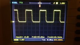
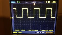
Im an idiot Perry forgive me fellas 😱 apparently so.... Good thing I hurriedly cut power. Seems like all is well is far as the caps heating. I got 12.8 to 13 vpp. square wave On pin 10 on pin 9 it was around 13.8 vpp.
Pin 10
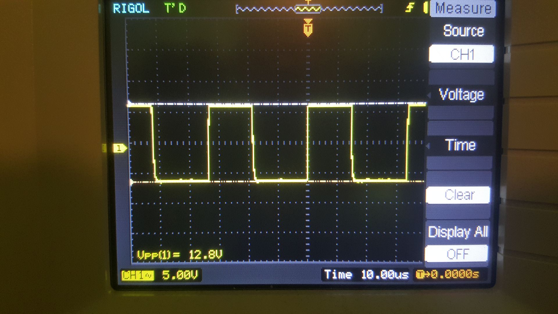
Pin 10
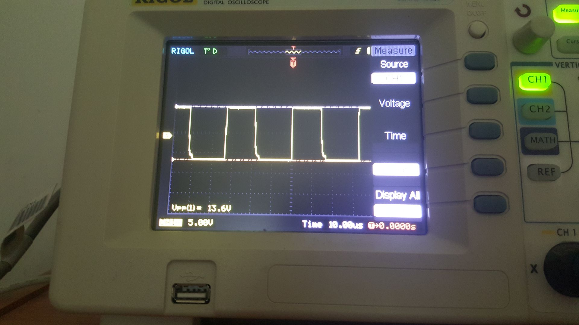
pin 9
I get a square 3.0 vpp on the signal side resistor legs R5 thru R8 but not the case on R9 thru R12.
R5 thru R8
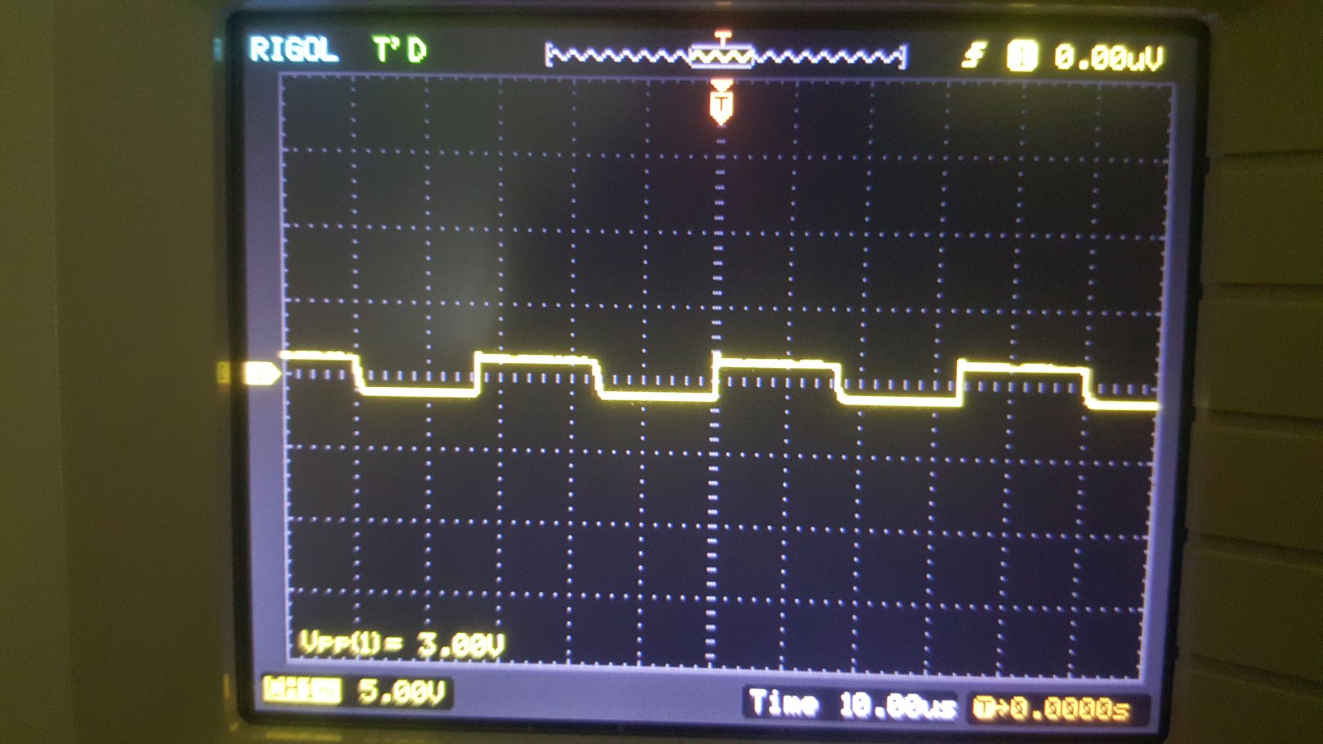
R9 thru R12
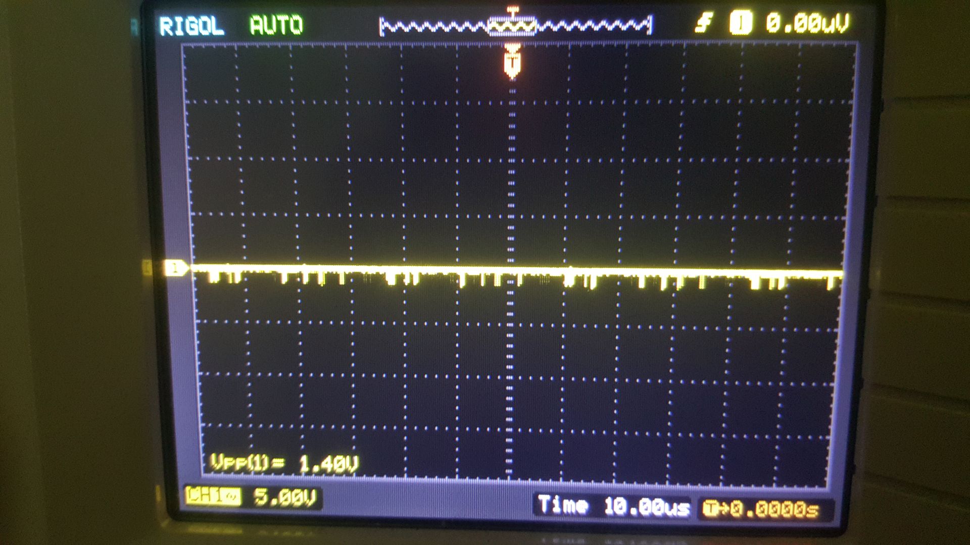
I get a square 3.0 vpp on the signal side resistor legs R5 thru R8 but not the case on R9 thru R12.
R5 thru R8
R9 thru R12
Last edited:
Looks like R9 thru R12 trace back to the emitter junction at q17 and q18. Thought maybe I damaged them through excessive heat while soldering so should I recheck them?
Last edited:
You need to set your scope to DC coupling.
Doesn't that scope have the ability to generate screen caps?
Doesn't that scope have the ability to generate screen caps?
Dc couple is on. Yes it has screen capture but it is hooked up to another pc whose internet is very slow. A real hassle to upload from.
Last edited:
It makes the waveforms useless because there is no reference. Please read through page 73 of the BCAE1 site, paying particular attention to the 'best initial settings' section (which includes the reason for DC coupling).
It was engaged at the time the photos were taken. Its choices are DC, HF reject, LF reject, and AC. It was on DC.
Last edited:
Ok I did a self cal and it set the scope to dc couple correctly I believe its set right now because the dc symbol; the dots over the solid line is whats in its place now versus "~" in my first scope photo.
Last edited:
Hi Perry,
Sorry for the delay. Here is Pin 9 left and pin 10 right.
Sorry for the delay. Here is Pin 9 left and pin 10 right.
Attachments
Last edited:
I also checked the 5 color bands of the resistors and got brown black black gold and brown. The calculator kicks out 10 ohms at 1% by the size Im just taking a stab that they are 1/4 watt.
- Status
- Not open for further replies.
- Home
- General Interest
- Car Audio
- Orion Extreme 500.4