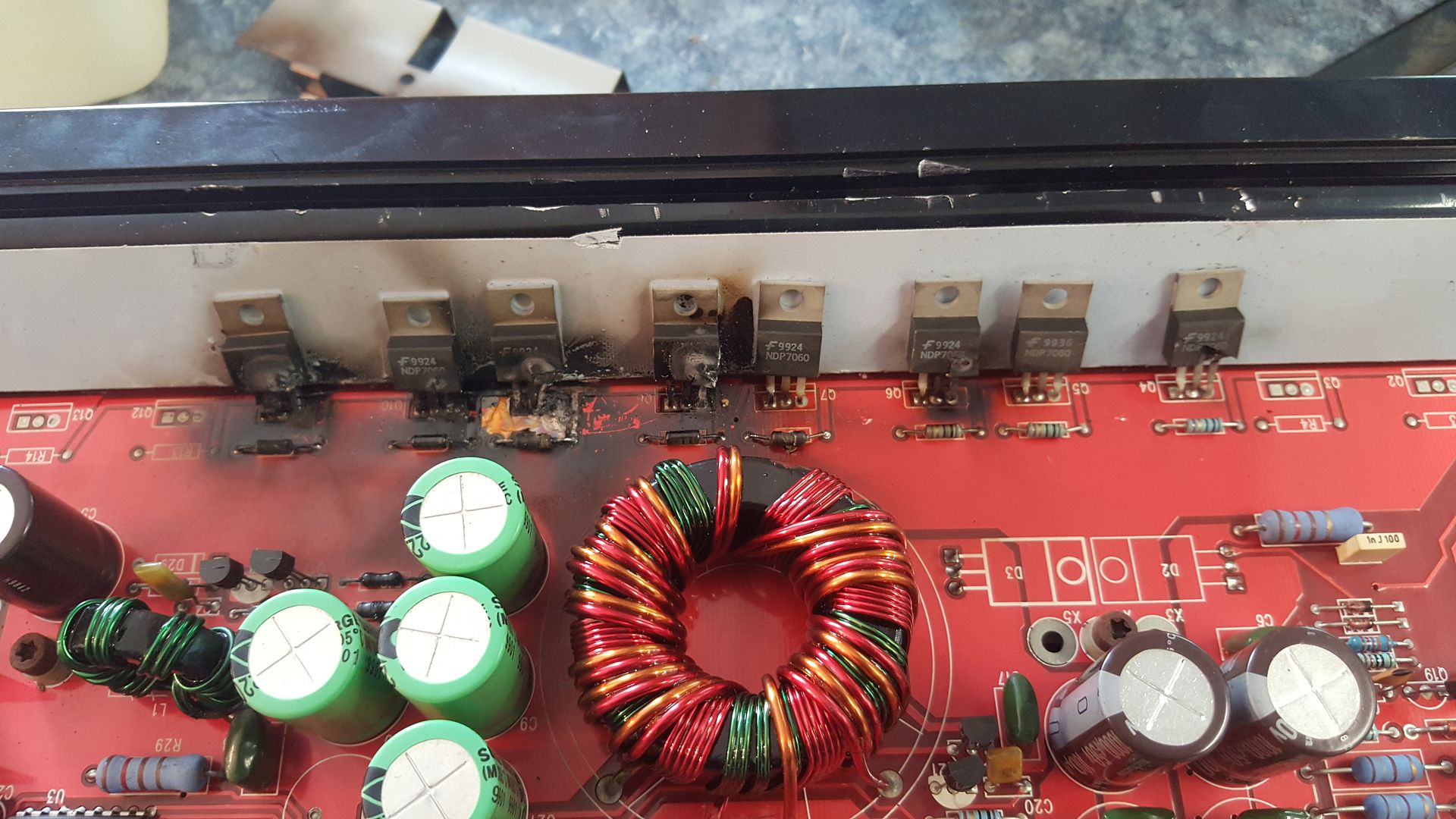
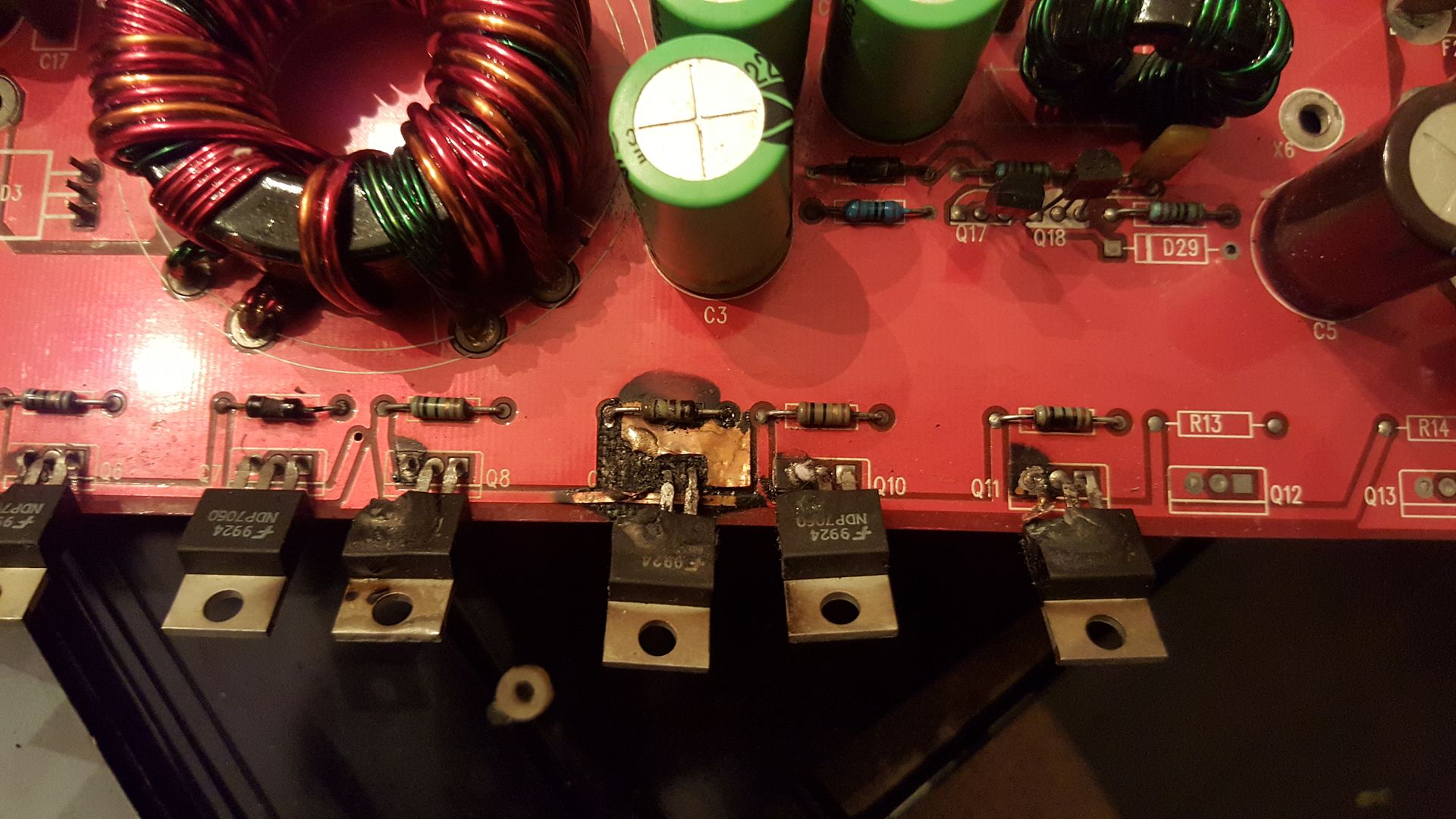
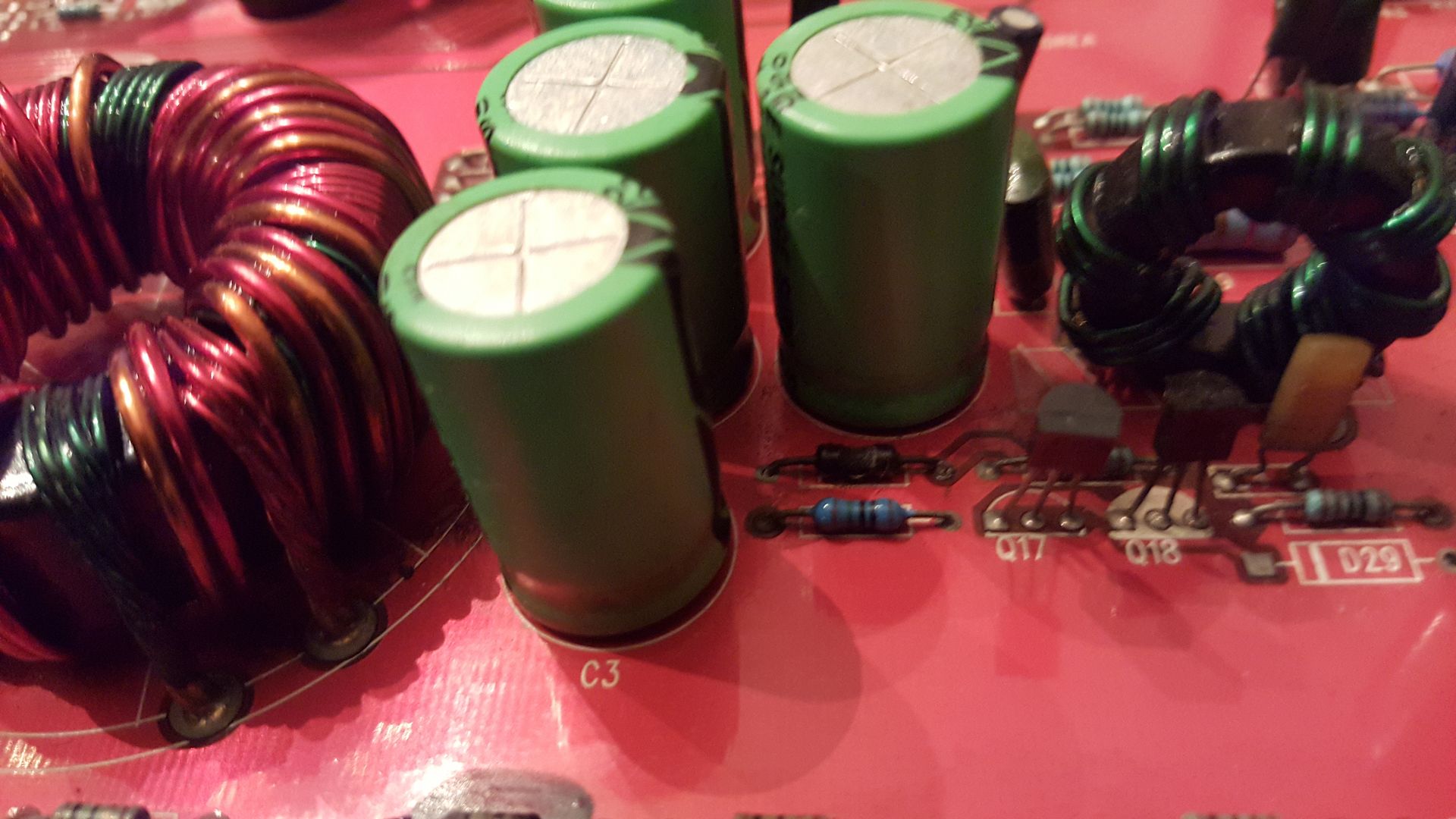
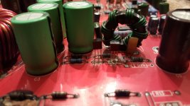
Obviously the power supply fets ndp7060 need to be replaced. Im also curious about q17 q18 and another component in front of the cap in the close up. So charred I dont know if it was a resistor or diode of some sort. Guess ill have to de solder a leg and lift it. The user did a pretty good number on this. Looks like ill have to work around some pcb damage on one of the fets.
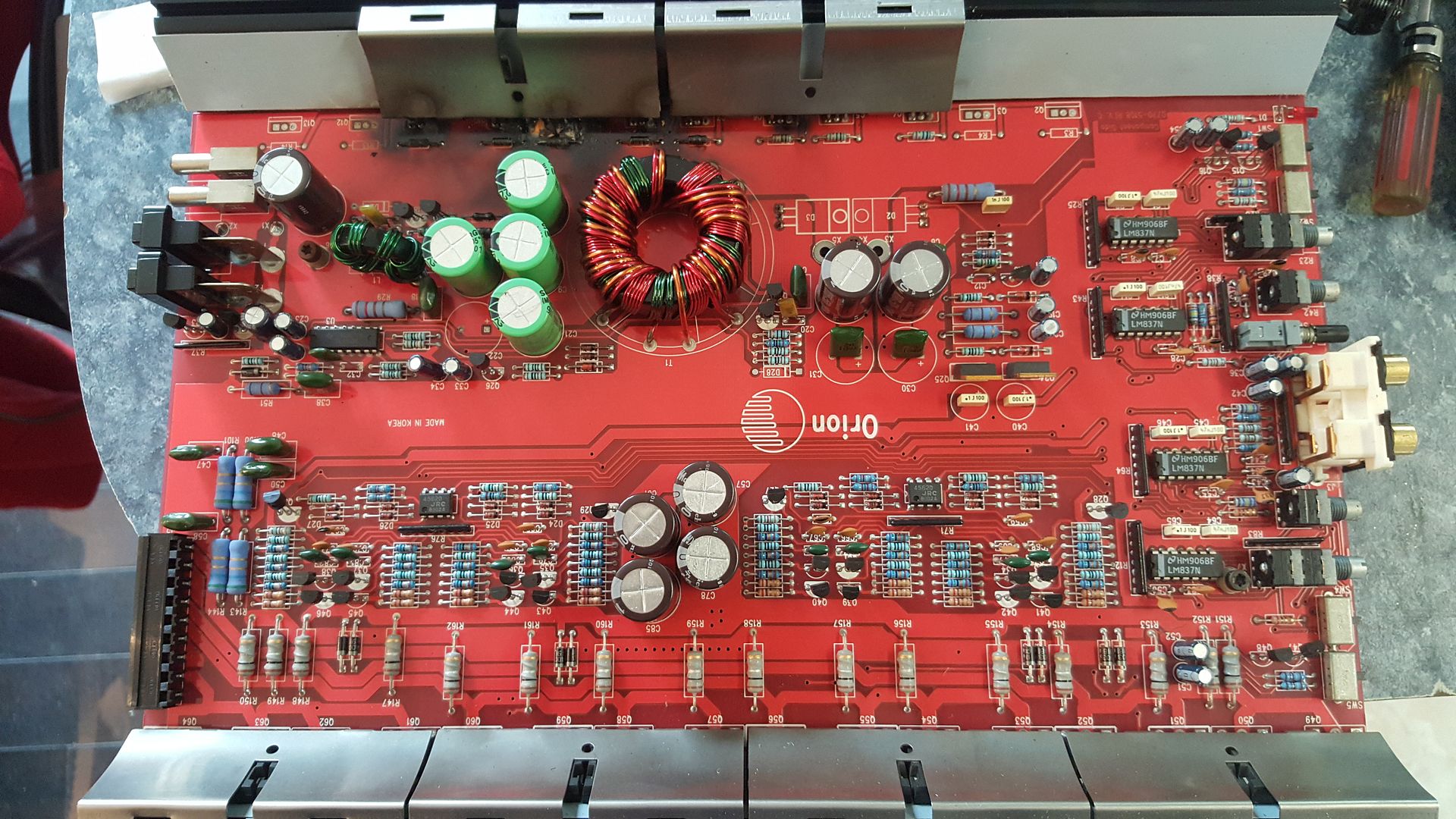
what is a reputable source for the NDP7060'S heres what I saw when I opened it up.

Thanks
Hugh
what is a reputable source for the NDP7060'S heres what I saw when I opened it up.
Thanks
Hugh
Last edited:
Cleaning the components cotton swabs and alcohol will help you identify them.
Any of the authorized distributors on octopart should be reliable (in that the parts are genuine). On the list below, mouser and digikey would be the ones I'd recommend.
https://octopart.com/search?q=ndp7060 #/search/modals/allPrices/e82b2124f9e137ec
Any of the authorized distributors on octopart should be reliable (in that the parts are genuine). On the list below, mouser and digikey would be the ones I'd recommend.
https://octopart.com/search?q=ndp7060 #/search/modals/allPrices/e82b2124f9e137ec
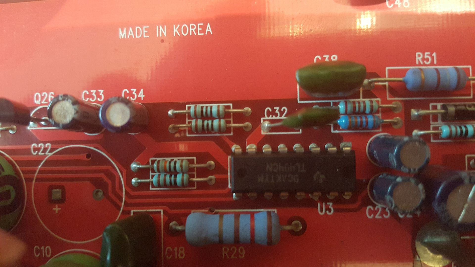
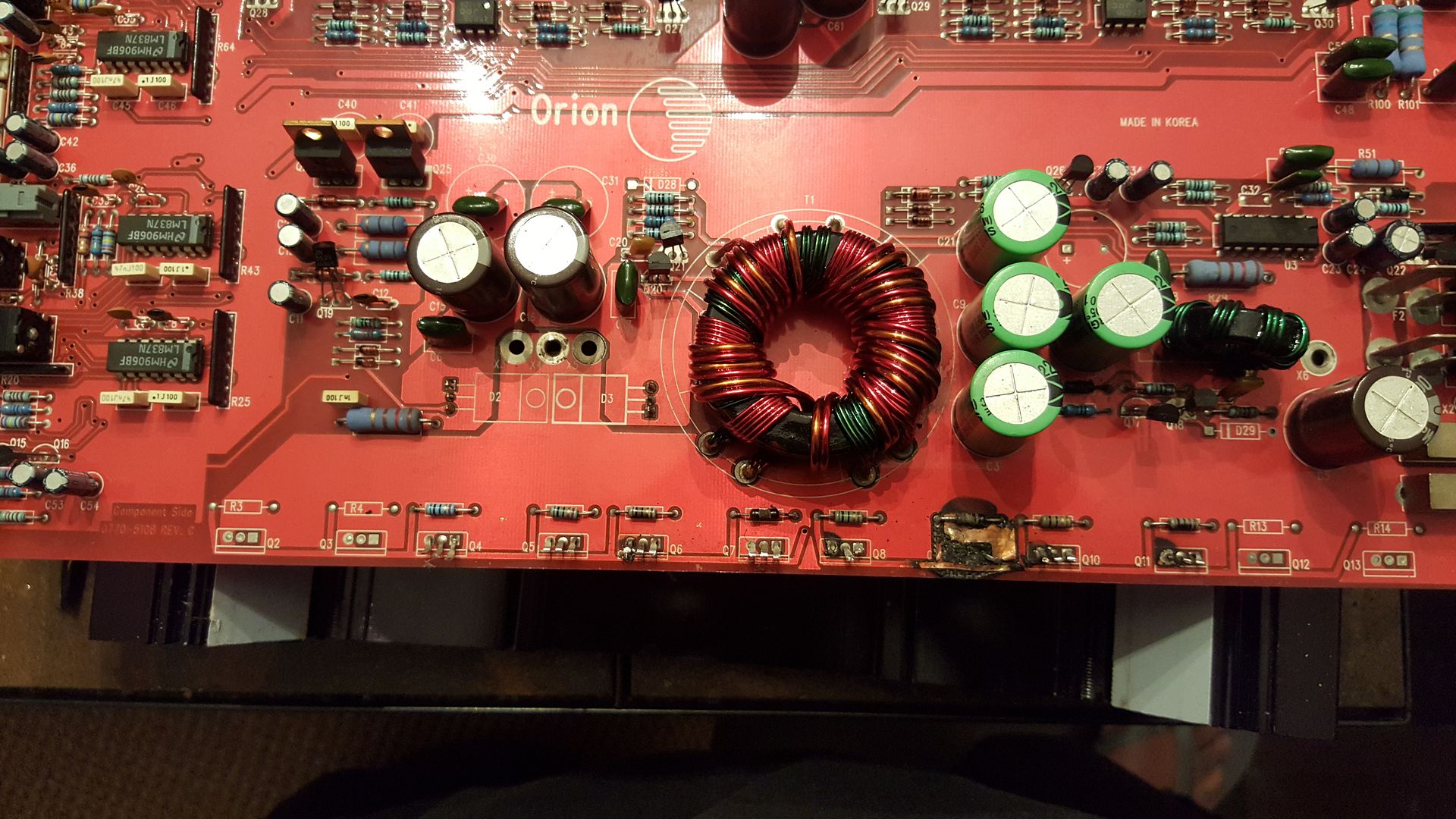
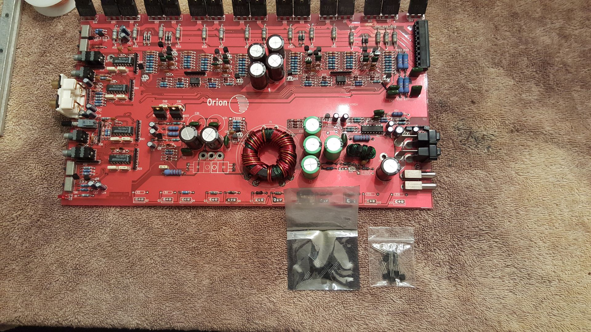
All cleaned up.
What do you think Perry? Should I immediately look at the power supply controller tl494? I think reverse polarity may have caused the failure not sure. Looks like a burnt resistor that I was worried about. I have no schematic so I have no idea what its value is. I guess I could still try to read it.😱
Funny how the case has made in usa but clearly on the board it says made in Korea. Great marketing scheme Orion.......
Last edited:
Not much as far as normal operation is concerned.
You could, however, use two of the unused locations (Q12 and 13) to install the FETs that would otherwise go into the badly burned locations (Q9 and whichever other location in the same bank that's badly burned).
You could, however, use two of the unused locations (Q12 and 13) to install the FETs that would otherwise go into the badly burned locations (Q9 and whichever other location in the same bank that's badly burned).
Not much as far as normal operation is concerned.
You could, however, use two of the unused locations (Q12 and 13) to install the FETs that would otherwise go into the badly burned locations (Q9 and whichever other location in the same bank that's badly burned).
Thanks Perry. Where would you start?
Hugh
Last edited:
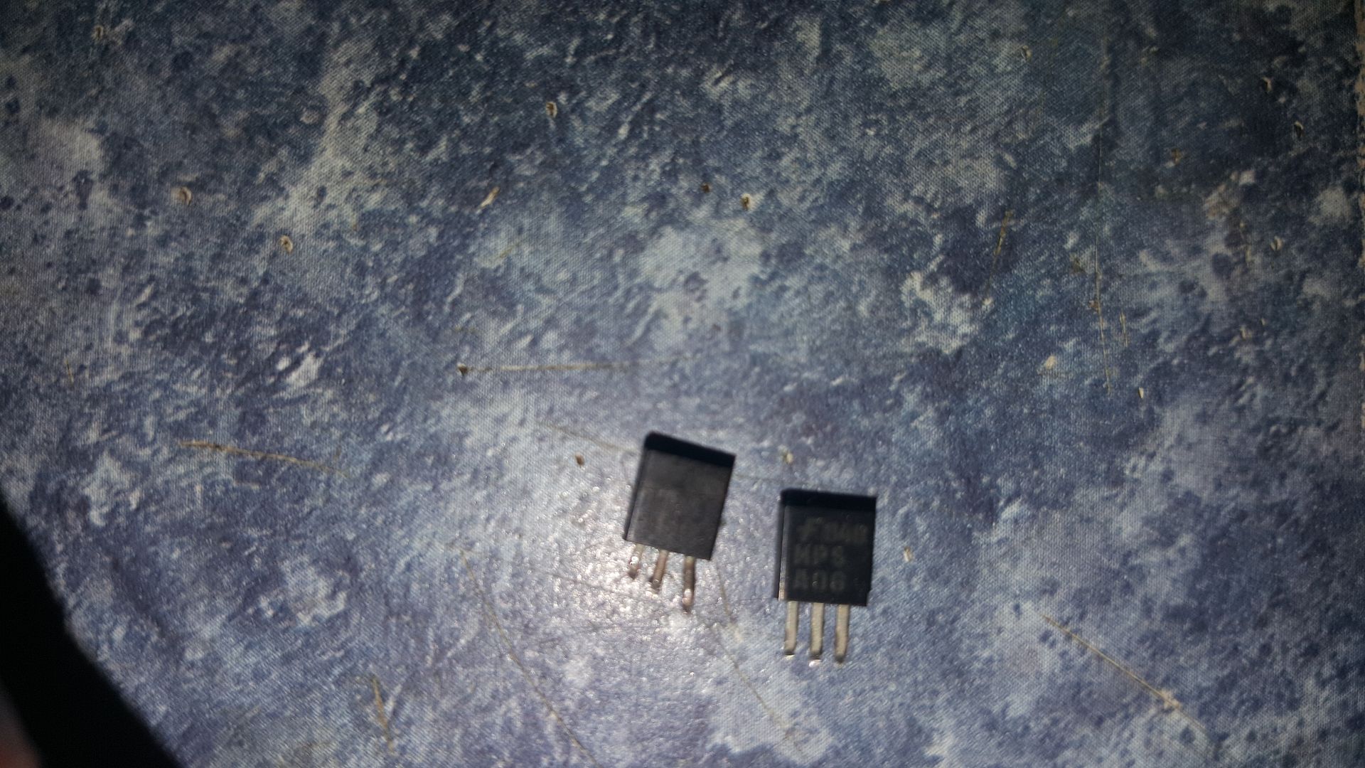
I can also see that Q17 NPN (MPS A56) is visibly damage so I guess I may as well replace it and Q18 PNP (MPS A06) looks like Im working my way back to the TL494CN.
Last edited:
It's unlikely that the 494 is damaged. With no PS FETs in the circuit, you should read approximately 5v on pins 9 and 10. You should read approximately the same at the bases of the driver transistors and at the gates of the FETs (after all drivers and out-of-tolerance gate resistors have been replaced.
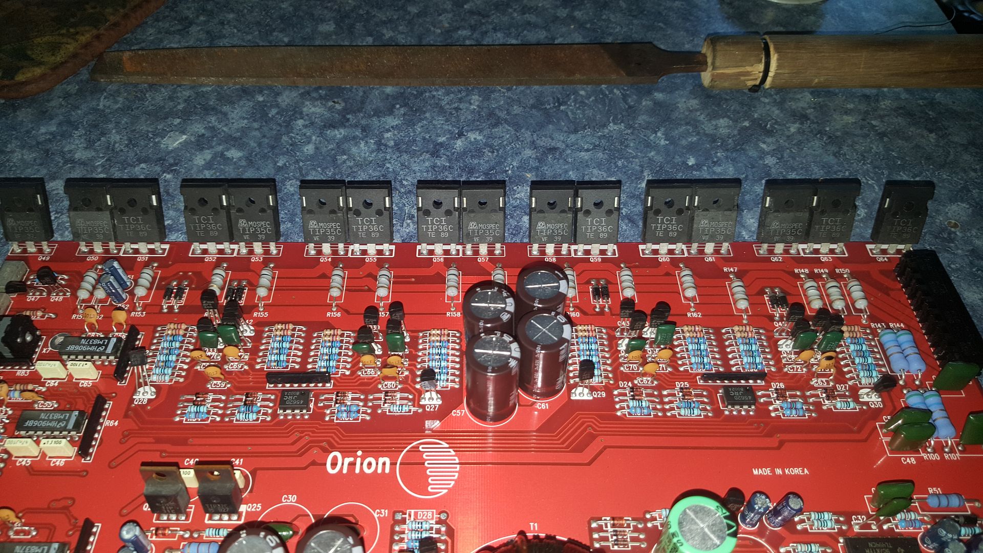
Have you checked the output transistors to see if any are shorted?
Have you checked the output transistors to see if any are shorted?
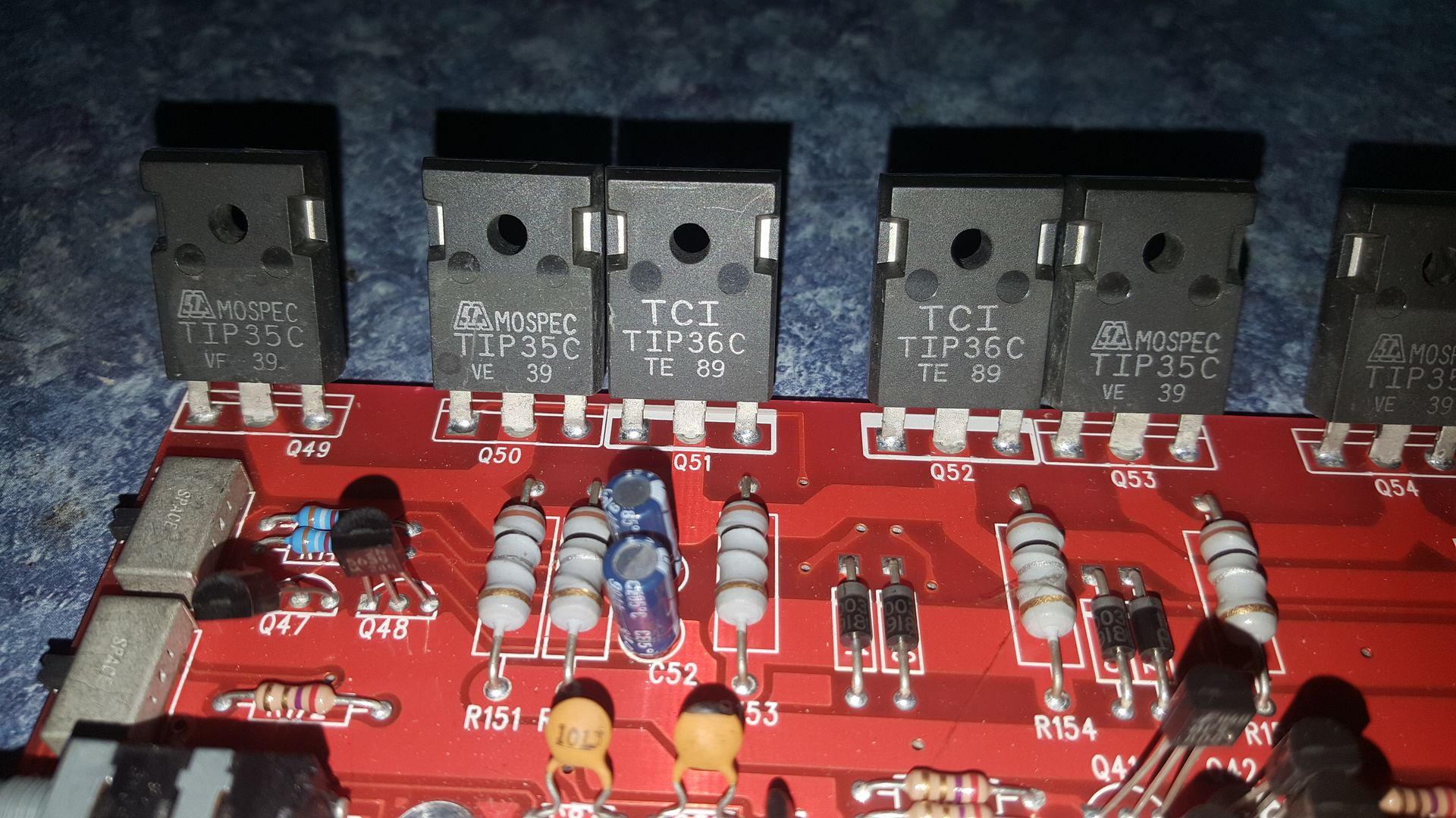
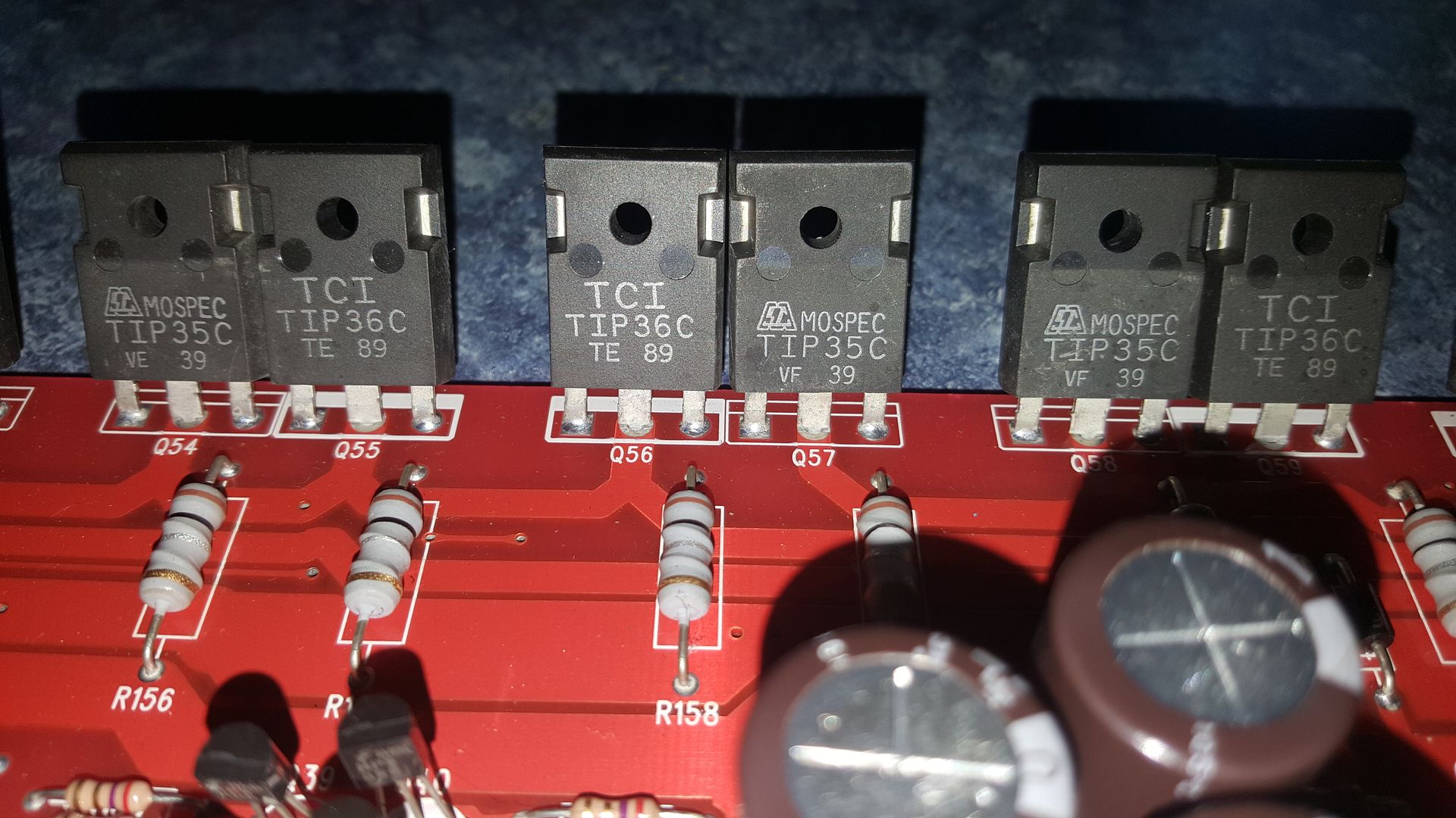
No more than a visual inspection so I probably need to but they are pristine in appearance. Really beautiful on that side of the amp with TIP 35,36 unions. I really think what happened is the system was installed by a shop and the user called themselves removing a sound processor out of the chain then went back and reversed polarity on the amp. I dont think this failure was a result of normal usage. They look so nice I hate to pull them and have nothing be wrong. Its always a bad sign when you received an amp and the fuses have been removed but the user tells you all I did is disconnect the radio😱. Sorry but I think it took more that that to burn this board up like it is. I dint say a word I just removed the amp, brought it back to the shop opened it up and the games began.
Last edited:
This is what I got across the gate resistors
R5 10 ohms
R6 10 ohms
R7 10 ohms
R8 9 ohms 🙂
R9 10 ohms
R10 10 ohms 🙂
R11 10 ohms
R12 10 ohms
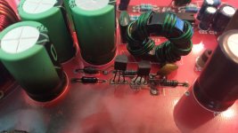
Over by the transistors and burnt one that is charred this is what I measured.
R18 150 ohms
R19 1k ohms
R21 10 ohms 🙂
R22 1k ohms
If you notice in the top photo R20 is an array on the left side bottom. Left of the bottom LM837N
Smileys denote badly charred but still giving a reading.
Last edited:
The resolution of the resistances given aren't sufficient to make any determination as to whether they're good or not. You don't need to repost them but you need to measure again. The resistors have value and tolerance bands. 1% resistors should be withing 1% of their marked value. 5% resistors need to be within 5% of the marked value.
You cannot determine whether the outputs are good or not without checking them with a meter. If they're shorted, they may cause the failure of the power supply when you apply power after repairing the supply.
You cannot determine whether the outputs are good or not without checking them with a meter. If they're shorted, they may cause the failure of the power supply when you apply power after repairing the supply.
Can I test the outputs without soldering any legs? What will I do with the resistor thats charred so bad there is no colored band to compare reading to?
Attachments
Last edited:
You can check the output transistors in the circuit to see if any are shorted.
Generally, only the driver circuit components are burned badly and there is generally a corresponding set of components/resistors for the other half of the drive circuit that may be in better condition.
Generally, only the driver circuit components are burned badly and there is generally a corresponding set of components/resistors for the other half of the drive circuit that may be in better condition.
In the circuit Q17 NPN (MPS A56) is damaged so it and Q18 PNP (MPS A06) will be replaced. Does it actually have to be these two or could I use a general npn pnp pair? Just curious as I think I have some others in my supply just not these specifically.
Last edited:
hifonics hugh said:In the circuit Q17 NPN (MPS A56) is damaged so it and Q18 PNP (MPS A06) will be replaced. Does it actually have to be these two or could I use a general npn pnp pair? Just curious as I think I have some others in my supply just not these specifically.
You can use any complementary pairs of transistors with same or higher rating. as long as the pinouts are correct.
Use Transistors with at least 500mA rating.
Watch out with the pinouts though as the MPSA06/56 have the BASE on the center leg and not the COLLECTOR
Thanks,
Luckily I found the direct parts replacements for fairly cheap. So I await them and the 7060NDP's
Luckily I found the direct parts replacements for fairly cheap. So I await them and the 7060NDP's
- Status
- Not open for further replies.
- Home
- General Interest
- Car Audio
- Orion Extreme 500.4