Connect only 1 of the red wires at a time to see if you can determine which half of the amp is causing the current draw.
You stated that the amp was drawing 15 amp from the power supply. Does the other half of the amp work properly (no excessive current draw)?
You stated that the amp was drawing 15 amps of current. Does the defective side draw 15 amps when it's connected by itself?
You stated that there was no voltage on the transformer. Was it drawing excessive current when you measured the voltage?
Where, on the transformer, did you place your probe?
You stated that the amp was drawing 15 amps of current. Does the defective side draw 15 amps when it's connected by itself?
You stated that there was no voltage on the transformer. Was it drawing excessive current when you measured the voltage?
Where, on the transformer, did you place your probe?
The right half of the amp does work correctly, no excessive current draw and it passes through a sine wave perfectly.
The defective side by itself does draw excessive current. Note that the 15A is just past on the current control setting of my power supply.
It was drawing excessive current when I measured voltage to the transformer. I would test one point at a time and leave the amp running for <5sec each point. When measuring from the input center tap of the transformer, I saw voltage on the top side, but not the bottom.
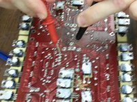
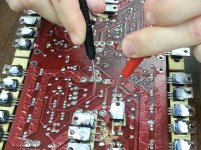
I think that you're going to have to post a photo showing where the probes were when you measured the DC voltage on the transformer.
In picture 147 I measured ~5VAC. In picture 205 I measured ~0. I am not sure how the transformer is wired so I do not know if this information is valid.
Note that the power supply was current controlled so it was only operating from ~5VDC.
Note that the power supply was current controlled so it was only operating from ~5VDC.
Attachments
This isn't a normal test.
Which of the transistors are getting hot when it's drawing enough current to drag the 12v supply down to 5v?
Which of the transistors are getting hot when it's drawing enough current to drag the 12v supply down to 5v?

I found 1 of the three shorted. I went ahead and removed all three and am noticing a short between where the collector and emitter pins would go. I made sure my output wires are not touching and am not sure what else in this part of the circuit would be causing the short; I did make sure there aren't any solder bridges.
I don't think that there is any component connected across the collector-emitter.
Are you sure that you have the pin configuration right?
Did you use a lighted magnifying glass to look for bridges? For some reason, Orion amps have a tendency to form a hairline bridge along the edge of the board.
Are you sure that you have the pin configuration right?
Did you use a lighted magnifying glass to look for bridges? For some reason, Orion amps have a tendency to form a hairline bridge along the edge of the board.
This was exactly the case, there was a bridge between pads on one of the parts. I replaced components and it tested well. I also changed out the gain pot as it seemed to be going out, now all is well and next step is to install in the car.
Thanks again for your help.
Thanks again for your help.
- Status
- Not open for further replies.
- Home
- General Interest
- Car Audio
- Orion 4100GX - right channel out