Forum
I liberated the amplifiers from a Saville solid state organ, which consists of 5 groups of 6, 20w amplifiers for a total of 30, 20w amplifiers. The power supply is seperate and voltage for the amps is 47v dc.
For testing I have one stereo amp pair connected up with the PSU and speakers. When the power is turned on, a loud fixed pitch sound is heard, which collapses over 3-4 seconds, then every thing quiet, and works well. I tried turning on the PSU first then the amps, but same result.
The PSU is typical old style metal chassis with transformer on top, full wave bridge.
The amps are open with a plate heat sink covering most of the PCB, no overall metal case or enclosure. Connection from PSU to AMP is two wire +/-, 47vdc.
The settup mimics the original setup when in the organ.
Any suggestions on how to prevent the initial noise?
Tuneturkey
Yes, its the same for all 5 of the amps on the same PCB, thats why i tend toward a power supply problem.
Do you think that it is a PSU filter cap? The capacitor is slow to charge up so the 60 hz ripple stays high until it finally charges up. makes sense!
Thanks,
tuneturkey
Do you think that it is a PSU filter cap? The capacitor is slow to charge up so the 60 hz ripple stays high until it finally charges up. makes sense!
Thanks,
tuneturkey
I don't usually start debugging a defective amp until all electrolytic caps are under 20 years old. Then if I still have problems, i get out the meter or scope and start looking for the problem. Usually I check DC voltages against the schematic, but lacking that. you can check your power supply voltages at 80% of what the capacitor rating is. Then check the b-e junction of the offending transistor that is about 0.6. Then if you still have oscillation not at 60 or 120 hz, use a scope or VOM or VTVM to track it down to a particular component. You have to put a .47 uf or .1 uf capacitor in series with the probe of a VOM to check AC, they read DC voltages on the AC scale otherwise. VTVM's come with a "RF" probe with a capacitor inside. A DVM is useless for tracking AC signals at non-power line frequencies. At least all the DVMs I have bought. A VOM, you can figure out the frequency of the oscillation with smaller and smaller series capacitors. Amps can have inaudible oscillations, too.
What are you going to use 30 20W amps for? I can't imagine you have a hall with 30 speakers in it. That arrangement was useful for multi-reflections of one oscillator organ sounds, but not much else IMHO.
See this about setting the bias current: http://www.diyaudio.com/forums/solid-state/136261-vintage-amplifier-repair-upgrade-manual.html
Last edited:
Indianago,
Well, I liberated everything from the organ that I could get off; amps, SAMS, powersupply, keyboards, everything but the wood console.
I am into Virtual , VTO, electronic organs and will use six of the amps with a delta 1011 soundcard on my theatre organ, and am midifying a moller console, modified to the horseshoe arrangement.
The Savile organ was based on the principal that there should be one amp for each 2, consecutive, notes, since adjacent notes are seldom if ever played at the same time. to go further, each amp powered a speaker mounted on a helmholtz resonator, a cardboard tube of diameter and length to match the frequency of the note pair,.With a dedicated speaker mounted on the end. Yes, there were 30 tubes with speakers from very small up to 15" speakers mounted on large tubes. Took a lot of space. It worked very well, with good blending of overtones, since the speakers played only one note. now you know!
I have in my possession a Dynakit ST 120, dual 60 watt amp which has been quiet for some time, but would love to have it playing to driver subwoofers for the 16' pedal notes. As I recall it was good down to 20hz with little rolloff. Do you do amp repair, etc.? i see from the list of equipment below your email that famous work Wurlitzer. whats the connection?
back to my original post, Would you start with the PSU filter caps, since the noise is common to multiple amps/
Thanks for the help!
Tuneturkey (in Baton Rouge, LA)
There was a thread about the Saville organ on organforum.com recently. Lots of people liked the sound.
Like I say, save time, replace all e-caps and clean connectors first. Then if oscillations remain, check all carbon comp resistors at actual value (they change). If that doesn't do it, then drag out the scope or VOM to trace remaining oscillations or other problems.
My adventures with the dynakit ST120 are detailed in here: http://www.diyaudio.com/forums/solid-state/156627-dynaco-stereo-120-can-beautiful.html
I handbuilt the 7 transistor djoffe design bias boards for the ST120 on perfboard that got rid of the cold crossover distortion, and love the improved sound. He won't sell PWB's of that mod, so making a good ST120 is not really economic at over $2 an hour. I also handbuilt the dual fan contraption that keeps it from melting the solder off the output caps if run to long at 10 W/ch (big fireball at church under the lectern). Djoffe is selling a ST120 - LM3886 IC conversion board on updatemydynaco.com, that shotguns all the old parts but leaves the heat problem to the user. His heatsink has no fins or fan, thus is good only for a limited time at wattage IMHO. If I were going into the business, I'd put one commercial finned heatsink crossways in the ST120, and one fan with a thermostat. My 2 fans on the ST120 run all the time, and if it wasn't behind the couch and I wasn't hard of hearing it might be annoying . However, heat and distortion problems are gone, I ran the ST120 17 hours a day for 18 months until I kicked the bias board in December and broke something. Should have put the top on. Got a PV-1.3k all over the coffee table, trying to invent a speaker protection circuit that actually does that instead of burning the lands off the PWB as previously designed.
The Wurlitzers were highly recommended by Paul0557 on organforum, are waiting complete re-e-cap. The 4500 whimpers a little, the 4300 makes a low moan without any keys down. At least they have hard key contacts at 170 Vdc. The main functional organ now is the Hammond H182 with the smashed case. 71 new e caps and some tab and drawbar cleaning really pepped up the sound on that. Was trying to play the H182 last night. I have poor pedal accuracy, still.
Question;
I have two 300w solid state amps, purchased on ebay, raw pcb with heat sink, no power supply. The amps were supposedly made by or for Acoustic Research, but have no labels, markings or other identification numbers. Are you aware of any such vendor? I have not attempted to power up since i don't know voltage or amp requirement. I will pull some data off the pcbs and add them to this thread. Possibly you can help me determine enough to get them running.
Thanks,
tuneturkey
If the power transistors have industry part numbers on them, you can download the datasheet from datasheetcatalog.com usually, and figure out what voltage they can run at. If the Vceo is a 10 ma spec, you can run PS rails about 1/2 that, but if the Vceo is a 50 ma spec, you need to run PS rails about 1/3 to 1/4 of that.
If the output transistors have private numbers, sometimes you can determine what they are by what date is on the capacitors etc. There are fads in transistors where everybody uses the same thing because it is the cheapest. How many output transistor pairs kind of determines how they did the 300 w spec. Current (I^2)*R is the power of a channel, and R is typically 8 ohms up to 1980 and 4 ohms after about 1980. If the amp is a car amp, the designed speaker resistance is 2 ohms or 1 ohm. The highest voltage capacitor on the PWB will tell you something about what service it was intended for.
I drew my own schematic diagram for the ST120 when I first repaired it, because there was no internet or other resource outside the Ham Radio club (and I don't talk enough to be a ham.) I would suggest you do this.
Acoustic Research was a speaker company in 1970 when I was buying speakers, and made a famous turntable. Then they went bankrupt, the name was sold somewhere, and like Dual (that was originally a turntable company) the logo might show up on anything, mostly imported. I didn't like their speakers much, too many watts consumed, not enough sound out.
If your output transistors have C#### or A#### on them, they are really 2SC#### or 2A####, because the Japanese found putting the first two letters on the part too expensive for words.
If you still want to silence your Saville organ amps. and the caps are new and the resistors are in spec, draw out a schematic and think about putting a power up reset circuit on it. My Peavey PV-1.3k amp has an input silence circuit that has an electrolytic cap timer (one junction transistor) that uses a jfet transistor to short the input to the power supply until the capacitor charges up. Schematic is on eserviceinfo.com, but this circuit is mainly for devices that have an op amp in the first stage.
Last edited:
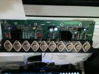
Ok - The unit has 5 ea MJ15024 (TO220) lined up on the left end of the sink and 5 ea MJ15025 on the right side. the leads extend thru the sink (1/4"thk) and on to the PCB. In the middle of the sink are three smaller transistors, a C168 on left, C158 middle and A958 on right. There are 2 small heat sink, 2"x2"x2', on left sitting on flatback transistors on the PCB. Also are 2 pair of transistors (T05) size. Electrolytics on the PCB are rated 100V. I have a photo of the unit, bu can't insert it. if i can find your email address, i'll send. Evidently, the PS capacitors were bolted in to the PCB, 4 each total , probably 3" in dia. The left end of the board has two plug on terminals labled LS1 and gnd , same on the other end. There is a 3 pin female connector on the component side of the board, and 2 on the back side, one 3 pin, one 4 pin.
Thanks,
Tuneturkey
Thanks,
Tuneturkey
This sounds fairly powerful. MJ15024 and 25 were TO3 steel case parts, according to recent datasheets. I thought Motorola TO247 (plastic, bigger than TO220) parts were prefixed MJL and MJW. Anyway, if the parts aren't counterfeit, you should be able to use +-75 to +-85v rails. If you are going to use that much, your speakers should be capable of half the rail voltage.
For 300 watts at 4 ohms you would need 8.7 amps at 34.7 volts. That would mean a power transformer of +-70 v rails. If your speakers are not that power capable, you can use lower power supply voltages.
The 2SA968 was in the Peavey PV-1.3k I just repaired, so the design time of this amp was about 1994.
For that much current you probably need at least 4700 uf @ 80v capacitors. The PV-1.3k has 10000 uf capacitors. I just bought some nice US assembled Panasonic 4700 uf 80 v ones from Newark.com rated 3000 hours life @ 85 deg c, ECO-S2AP472DA. You'll have to build a little board to strain releive the wires you solder to the snap in cap terminals. I use 1/16" or 1/8" thick LE laminate from mcmaster.com, which I can saw up with a sabre saw and drill with ordinary HS steel bits.
Whether your power transformer needs single 17 a winding or dual 8.6 a windings depends on whether this is a flying rail amp like the Peavey designs, or emitters and emitter resistors are connected to the speaker hot like more conventional designs. The conventional designs can use a single winding transformer.
Altenative to the power transformer/rectifier idea, you could buy a switching power supply. audiopower of italy was promoting their dps-400 400 W model on power supplies. and connexelectronic in hong-kong has his own section of the vendors forum below on diyaudio. These switching supplies would have to be in their own ventilated steel box to keep the howl out of the audio part, IMHO. Peavey put the switcher power supply in a separate steel box in the CS800s, I own one.
Last edited:
Indianajo,
Thanks for all the tips.
See attached.
Since I know how now, i'll take some better pics and send.
my intent when i bought the two amps was to use them with subwoofers for the 32' stops on my organ. In a room environment, I doubt that i would need 300 watts, however, I read data on a pcb that adjusted output watts to provide a flat response at lower frequencies. probably not doing justice to the PCB, bu anyway.
What puzzles me is why 4 large caps. i can see two, one on the + supply supply and one on the - supply. looking closely at the traces, the two middle caps are connect together, outter to connected together.
Attachments
If the caps are connected + to -, they could have saved money by buying lower voltage caps and stacked them to make the voltage rating. However if the speaker minus are connected to the middle point, then that is the middle of the voltage stack.
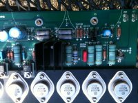
those transistors are TO3 package or metric variant, those output transistors could be genuine MJ15024-25.
If you want to save electricity dissipation in the heat sink, you could use a more conventional +-50 or 55 v supply.
Does the power feed connect to the tie point of the capacitors? Is the power feed 3 wires, (+,signal ground, -) or is the power feed two wires (+,-)? Some old designs use a single voltage supply, but that was rare by the days of the 2SA968. What value are the on-board capacitors? Some amps need a second pair of capacitors for the lower voltage for the input transistors.
If the heat sink under those transistors is 1" thick, it is just barely adequate for a 400 w amp with a big fan, IMHO. At +-50 volts or so you can use less fan for less no-sound noise.
new data,
I found writing on the PCB which says; Acoustic Research, P/N 18110550, Rev.B
Also found printed text; NC-1, 5192, 94V-0
The two transistor pairs are A1370 and C3467
There is one round silver IC can asymbol square with a filled in right arrow in it, AD, 711BH, 9229 delta symbol
I found writing on the PCB which says; Acoustic Research, P/N 18110550, Rev.B
Also found printed text; NC-1, 5192, 94V-0
The two transistor pairs are A1370 and C3467
There is one round silver IC can asymbol square with a filled in right arrow in it, AD, 711BH, 9229 delta symbol
Attachments
The 2sa1370 and 2sa3467 transistors are internal to the amp, they won't determine the power rating. Same with the Analog devices part, probably on op amp. You would only have to look those up on datasheetcatalog.com to repair the amp.
If the printed text 94 and 0 are next to the input power supply pins, then that is your supply voltage. If not, I don't know. You can get 94 and 0 out of a +-45 or +-50 v transformer, the higher voltage gives higher current flow on 94 v. You have to tie not use the center tap and bridge rectify the two ends of the transformer secondary into the main storage capacitors. Requires a higher main capacitor voltage than 80 v, however.
If the printed text 94 and 0 are next to the input power supply pins, then that is your supply voltage. If not, I don't know. You can get 94 and 0 out of a +-45 or +-50 v transformer, the higher voltage gives higher current flow on 94 v. You have to tie not use the center tap and bridge rectify the two ends of the transformer secondary into the main storage capacitors. Requires a higher main capacitor voltage than 80 v, however.
Any guess where I might find a schematic? Acoustic Research did market some integrated amps. Could these be extracted from one?
The two holes where the capacitor would fit show marks of a screw terminal. the other two are clean. The small electrolytics on the board are all rated 100v.
1994 also appears with the p/n .
Since the board is not well annotated, the LS1 lugs must be the speaker connection points. There are 2 sets, one on each end of the board, and they are connected together.
since there are 3 connectors, it is hard to say which is for inputs.
I suggest if google cannot find a schematic diagram for you, that you draw one. Google found the schematic for one of my amps here, the other on eserviceinfo.com. If your amp is part of a receiver or a powered speaker, you have to download the whole thing and just look at the pages for the power amp.
You really need to know how the speaker and power supplies are connected to buy a power transformer and main caps. If the speaker hot is connected to the emitters of the output transistors through a small coil, and the speaker negative to the middle of the two power capacitors, then it is a conventional post 1975 split supply amp. If the speaker negative is connected to the most minus power supply, and the the speaker hot goes through the coil to a big capacitor before going to the OT emitters, it is a single supply amp.
The input hot will be connected through a 2.2 to 10 uf cap to the base of a small transistor. The speaker hot is usually connected through a high value resistor to the base of another small transistor near the first one. (feedback).
Screw terminal capacitors are very expensive. I use radial lead snap in caps in the large sizes. You have to drill a board for a strain relief on the wires, because they don't grip the snap in terminals naturally. The snap in terminals go through the board, too. I mount radial lead caps to the metal case using glue- silicon caulk from Family Dollar store is what I am using now, although it is a pretty good copy of GE white kitchen silicon seal. The kind of silicon seal rated for 400 deg F, which is 100% rubber and no filler. Wall board adhesive also works, although you have to drive to the home store to buy it and a partial tube hardens faster than silicon caulk. Silicon, you can dig a hard plug out of the applicator with a small screwdriver.
Your output transistors are showing a date in the fall of 1992 - 9234.
Last edited:
- Status
- Not open for further replies.
- Home
- Amplifiers
- Solid State
- organ amp power on noise