Greets!
At this point I'm not clear as to the details of what you're building, but I'm a big proponent of EBS alignments IF they're tuned low enough to blend with the boundary/room gain to offset the loss of linear excursion power handling to achieve a ~flat in-room response.
GM
At this point I'm not clear as to the details of what you're building, but I'm a big proponent of EBS alignments IF they're tuned low enough to blend with the boundary/room gain to offset the loss of linear excursion power handling to achieve a ~flat in-room response.
GM
Sorry for the confusion. 2.86m folded pipe, no taper, pipe area is 1864 cm^2. This should give nice even response down to about 30Hz or so. In sim'ing I noted that a longer line could give response similar to EBS and get me another 1/2 8va or a bit more.
I will build the 30Hz version first as that should make a pretty nice sub of reasonable size.
mike
I will build the 30Hz version first as that should make a pretty nice sub of reasonable size.
mike
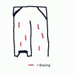
This is a crude sketch (I need to download a drawing program) of the layout. I think I should probably include some bracing. The red lines are what I have in mind for bracing. Somewhat randomly placed sections of MDF or 1x boards. Is that the kind of thing that I should do? Should the edges of the boards be radiused for smooth airflow or does it really matter?
mike
mike
Attachments
Greets!
True, or you can either reverse taper the line or add a vent at the open end. FWIW, my best results were from reverse tapering the pipe (TQWT) and fine tuning it with a straight vent pipe, allowing <20 Hz tunings in much smaller cabs than a (folded) straight pipe.
Unless the brace boards are really thick and/or a wide BW alignment is desired, it's not an issue since the WLs are so large WRT the pipe's CSA that they're acoustically invisible. FWIW, on large CSA pipe designs I just ran a vertical angle iron down the sides offset horizontally in a golden ratio (1.000:1.618). Note that I used no-void 3/4" marine grade ply, a suitably rigid cab material to ensure mass quantities of bracing wasn't required.
GM
Great. I have a bunch of 1x4 pine boards lying about so I will probably use them for bracing. When you speak of a port at the open end do you mean closing it off partially and leaving an open port? How do you go about calculating that? Would such a thing lower the sensitivity too?
I am planing a trip to Lowes after payday. 🙂 Will need more MDF and some clamps. Can't wait.
mike
I am planing a trip to Lowes after payday. 🙂 Will need more MDF and some clamps. Can't wait.
mike
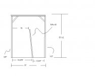
Well I still haven't gotten the NDF that I need to build this thing but it might be just as well because I have modified it a bit. Right now I am planning on making it a 2.0 taper line which ends up giving a little bit more space efficient package. I also found a program that lets me do screen captures of the full screen EGA graphs that the simulation program makes so I can post the latest sim results.
I am including a picture of the layout as I planned it using the scraps I now have but I think I will wait and get some 3/4" material so that I can do it right. The pic gives the general idea though.
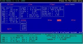
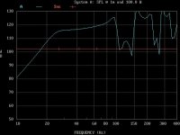
In the next two posts I will include the design parameters and the simulated response plot at full Xmax at 25Hz (assuming an estimated xmax of 6mm).
I am including a picture of the layout as I planned it using the scraps I now have but I think I will wait and get some 3/4" material so that I can do it right. The pic gives the general idea though.
In the next two posts I will include the design parameters and the simulated response plot at full Xmax at 25Hz (assuming an estimated xmax of 6mm).
Attachments
mashaffer said:When you speak of a port at the open end do you mean closing it off partially and leaving an open port? How do you go about calculating that? Would such a thing lower the sensitivity too?
Greets!
Hmm, I thought I responded to this. Anyway, yes. You'll need to model it using MJK's or similar Mathcad software. Yes it will, just like when tuning a BR real low.
GM
- Status
- Not open for further replies.
- Home
- Loudspeakers
- Subwoofers
- Or maybe a TL