I am planning a conventional push-pull tube amplifier with 807 output tubes. I intend to linearize the output by applying feedback from the secondary to the cathodes of the output tube, and an UL tap 33% from the anode.
The first stage will be probably a pentode (E83F or E180F) and I would apply global negative feedback from the output to its cathode.
The phase splitter is a dual triode long tailed pair, with a current generator in the common cathodes.
What I am thinking about, how shall I distribute the gain between the input stage and the phase splitter stage for minimum distortion. If I keep the gain of the first stage low (by large cathode resistor > local feedback), then it can work at low distortion. But then its output signal will be too low, and the gain of the phase splitter must be increased. In this case the distortion of the second stage would be dominant.
My idea is to adjust the gain of the first and second stage for minimal distortion without GNFB, and apply the GNFB after everything works fine. I am planning some 12 dB GNFB, i.e. the open loop gain will be about 4x the closed loop gain. The open loop input signal would be 500mV for full output power. But the question is how shall I distribute the gain between the first and second stage?
What you are proposing is an Oxymoron.I am planning a conventional push-pull tube amplifier with 807 output tubes. I intend to linearize the output by applying feedback from the secondary to the cathodes of the output tube, and an UL tap 33% from the anode.
An 807 can't be a "conventional PP amp", it's a valve that very much likes to be driven into AB2, or large amounts of g1 current, as it's a transmitting valve.
Add to that it is very prone to snivets- strong HF oscillation because of the short electron stream but the long cables of neccessity from the TC anode to the OPT.
807s don't like being run in the way you describe, because they have a very insensitive aligned screen grid, but which can't really be run much higher than 300-350V.
At this voltage they are far from optimal, which is why Williamson decided to run its more powerful (higher voltage screen cousin) the KT66 as a strapped triode at 400V, as which point it resembles an early Osram DHT.
(807s are an uprated 6L6 which is a valve that doesn't work well in UL mode).
Also production spread of 807 are enormous, and the anode constructions are far from standardized.
Further to that, the 807 produces a lot of nasty odd harmonic distortion in PP, which is why they fitted it with a top cap, so that you could jack up the anode to well over 600V, where it does start to lose the high harmonic distortion behaviour, and sound a lot better.
Add to this, if you insist in using cathode feedback, because of the low GM of the valve you will push the drive requirements of this valve through the roof.
Is that what you want to achieve,(?) because if you do, you can end up with a lot more distortion than you bargained for, which won't be cured with NFB, that will just quite easily turn it into a HF transmitter...
Last edited:
...feedback from the secondary to the cathodes of the output tube, and an UL tap 33% from the anode....
Each of these steps will roughly double the drive needed to the grids. Together they make 4 times more drive than a straight amp. As the 6L6/807 is not totally easy to drive straight, 4X more drive is beyond the reach of even a good driver, unless worked at higher B+ than the power stage (which is awkward).
I have no difficulty at all driving my 807 amps to 75W in AB2 perfectly cleanly, but it requires 100V of drive, achieved with a cathode follower and CT choke feed.
You can work this out easily by determing the 807 requires 30-32V of bias per valve.
So, in order to reach 0V at the grid you need 64V of drive.
With 100V of drive that means the grids will be driven 18V positive, but the A-A load needs to be halved to get there.
If you add 18V of cathode feedback (say) that would mean you would still need 100V of drive but it would effectively end up in AB1, which gives you at least 35-40% less power, - MAX 40-50W
If you use a lower anode/screen voltage, and try to run as a triode or in some form of ultra linear you will lose another 50%, so you would struggle to break the 20W barrier even with a lot of drive.
I found a typical high quality output transformer could quite easily be used as a CT choke feed also, with the added advantage of giving a headphone output on the secondary.
I believe the 807 was originally designed to be used as an RF amplifier, as well as an Audio Modulator amp, for communications service. Communication modulators generally did not have 20 to 20k bandwidth.
The 807 is similar in some ways to the 6L6, but designed for a different purpose.
Original 6L6 screen rating was 270V, the newer 6L6GC has a new screen design and is rated for 450V.
(Some do not like the sound of the 6L6GC over the earlier 6L6 types; some do not like brussel sprouts, 12AX7s, KT66s, SE, PP, etc.)
Original 807 screen rating was 300V, that was revised to 400V in triode mode.
807s were regularly used with control grid current.
6L6s were not intended to be used with control grid current.
Your mileage may vary.
The top cap is there to:
Get all the other tube connections away from the plate connection, so that the RF tank circuit could be above a metal plate and tube socket, and the socket tabs and other connections could be below the metal plate.
The tank circuit, very high impedance, was located in a metal 'box' to keep arcing to a minimum, and keep the Q of the tank circuit high.
Military and Amateur transmitters, anybody?
Yes, the 807 is and can be used for Hi Fi amplifiers. Ampex, Manley, Heathkit, and many others used it. It just requires attention to some details.
"All generalizations have exceptions"
Last edited:
Yes, the 807 is and can be used for Hi Fi amplifiers. Ampex, Manley, Heathkit, and many others used it. It just requires attention to some details.
And was DTN Williamson's choice for the American version of his signature amplifier.
All good fortune,
Chris Hornbeck
The 807 is a 6L6. The structure is identical, but they made some major changes to the rigidity of the device as well as anode materials & internal screening.The 807 is similar in some ways to the 6L6, but designed for a different purpose.
Original 6L6 screen rating was 270V, the newer 6L6GC has a new screen design and is rated for 450V.
(Some do not like the sound of the 6L6GC over the earlier 6L6 types; some do not like brussel sprouts, 12AX7s, KT66s, SE, PP, etc.)
Original 807 screen rating was 300V, that was revised to 400V in triode mode.
The top cap is there to:..........
As a result it can be run for hours red plated with no apparent harm.
On these ancient 1930s valves, the screen was aligned. This made them highly efficient, much more so than the Philips designed pentode.
As now mentioned a few times, the true anode in a 5 element valve is the SCREEN grid. The main anode - in the case of 807 connected to the TC is a virtual anode.
The behaviour of beam tetrodes is interesting as the anode voltage dips below that of the screen.
In the case of triode connected 807s, the screen will follow the anode, giving it that unique signature of strongly dropping gain as it drops below 270V, so the interesting area is in the place where it most risks destruction* (270-400V as a triode).
Clearly the 6L6GC (and of course the KT8/KT66) with their larger cathodes get this extra 50V above 400V as an extra large "triode strapped" window, which of course is why Williamson did it, then he bolted on masses of NFB, and the extra pre OPV gain stage to get around all the disadvantages.
It's obvious in retrospect to see why Williamson amps made good oscillators.
Coming back to the 807.
Thanks to our friends at Bogen, we could see what happens when you start to use that top cap (TC) for what it's really designed for. (Dangerously high voltages).
As I just mentioned, the 807 has this small window as a triode, below which it starts to lose gain pretty drastically (it's an ancient low gain valve requiring shed loads of drive), and becomes inefficient.
Used as a beam tetrode (some say pentode), the classic sonic signature remains pretty lacklustre with high 3rd harmonic and IMD, like the 6L6, until you jack the anode voltage sky high into pretty much (ICAS) figures.
It's not recommended to do this with anything other than the 807 & KT8C. (A high voltage KT66).
Bogen ran some of their PA amps at 835V on the anode, which is so scary to work with you can easily get arcs jumping around the PSU.
At 600-900V on the anode, (with a 300V stabilised screen) driven hard the 807 sounds truly wonderful.
I suggest this is because of the internal gain of the device, becoming optimal with the anode swinging between 400v>850V, or a good 100-500V above the screen grid.
I suggest this drastically reduces the odd order distortion.
+
Clearly run in AB2 on full drive you are getting voltages on the TC on cutoff of well over 1500V.....
FYI.
I did revalve a couple of Ab2 hifi amps with KT8C instead of 807.
Not a particularly easy thing to do, inc changing the bases to B5.
TBH, it didn't seem to make much difference sonically.
Last edited:
According to the Philips QE06/50 datasheet http://www.frank.mif.pg.gda.pl/sheets/030/q/QE06-50.pdf (the 807's European designation), this tube is well suited for AF applications in class AB (zero grid current) as well as in class AB2 (more than zero grid current) with very low THD at 2%. Due to the screen voltage rating of just 300 V, UL isn't that simple, requiring a dedicated OT winding. And yes, this tube demands large drive signals, most probably due to it's rather small cathode and low heater power (compared to the EL34, for instance).
Best regards!
Best regards!
It's well known the 6L6 does not work well in UL, because of the relative insensitivity of the screen.According to the Philips QE06/50 datasheet ....very low THD at 2%.
Due to the screen voltage rating of just 300 V, UL isn't that simple, requiring a dedicated OT winding.
And yes, this tube demands large drive signals, most probably due to it's rather small cathode and low heater power (compared to the EL34, for instance).
I don't know how they can claim such low distortion, - even the KT66 is incapable of that.
The small cathode has nothing to do with gain, that is all set by the grid spacing and internal structure.
There's lots of high gain valves with small heaters.
The EL34 was derived from the EL37, specifically manufactured to have 2-3x the gain of the 6L6 in order to make driving it easier.
Well, I don't suspect them to have thrown the dices. Do you, really?I don't know how they can claim such low distortion…
Especially in screen grid valves voltage gain roughly is proportional to gm. According to Heinrich Barkhausen, gm is defined by the cathode surface area, the distance between cathode and grid and the grid's winding pitch. I'm quite convinced that the EL34 designers chose a larger cathode to ease driving this tube. Or for whatever else reason might they have increased the heater power by 67% in comparison to the 6L6 with approximately the same cathode current rating?The small cathode has nothing to do with gain, that is all set by the grid spacing and internal structure.
Best regards!
Last edited:
Well he was wrong.According to Heinrich Barkhausen, gm is defined by the cathode surface area...
I'm quite convinced that the EL34 designers chose a larger cathode to ease driving this tube.
Or for whatever reason else could they have increased the heater power by 60% in comparison to the 6L6 with approximately the same cathode current rating?
The 6L6 has a 0.9A heater (The 6V6 is half that, and works pretty well.).
The KT8 has a 1.27A heater, and served as the prototype for the KT66, which has the much larger cathode, but has the same gain exactly as the 807/6L6. (6ma/v).
I have used these quite a bit in Ab2, the only novelty being the ONLY power output valve I know, where you can peer in through the transparent bottom, by the pinch and actually see the electron stream being modulated between the beam plates with your own eyes.
The KT66 has a double sized cathode compared with the 6L6/807, with almost the same heater demand as the (1.5A heater) EL34, the only thing being improved over the KT8 was to be able to use a higher screen voltage, but limited Anode supply thanks to having no TC.
The larger cathode of the GEC KT series valves made no difference whatsoever to the gain or current carrying capacity of the design.
That was set in stone by first Harries, then RCA in 1936, and is still being made like that today.
GEC made their own "EL34" which has a 1.4A heater, - the KT77, which resembles the US made, 6CA7.Both are beam tetrodes.
They have the higher gain of 11ma/V, like the EL37 (pentode) but are much smaller, looking like the EL34.
KT77/6CA7 probably doesn't have the achilles heel of the EL34, heavy g2 emission which burns them out, and makes them blow up.
The only way you will get better performance of 807s is by fitting a QUAD of them, which doubles in effect the transconductance.
Using the classic 807 is nigh on impossible, because of the size & huge production spread.
I have great success by using the little STC loctal version which is half the size, and has much tighter mil spec tolerances.
Those also have the lowest inter electrode capacitance of them all, thanks to the compact Loctal base, and the tiny top cap on the 4m version, which enables you to push 800V REAL, instead of the "let's pretend"* of the EL34.
I particularly like the 5m version which has the anode coming thru the base, giving very short wires into the OPT. All this stuff is pretty common knowledge..
*(They ran EL34 PA amps in Mullard works at 800V and they blew up constantly!)
Last edited:
Then it's NOT damned well identical, is it!The 807 is a 6L6. The structure is identical, but they made some major changes to the rigidity of the device as well as anode materials & internal screening.
Are you trying to be "smart"?Then it's NOT damned well identical, is it!
When was the last time you took one to bits??
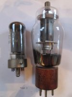
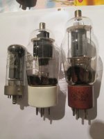
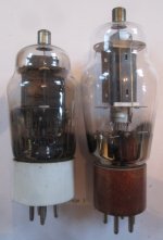
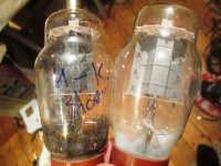
You can see here they are identical to whichever flavour of 6L6 you fancy on that day.
Grey plates, black plates, or 6L6GC innards stuffed inside.
The 255M on the left without the TC, is a high voltage 6L6 with a loctal base.
You can run it at 800V, which I doubt you can manage with a 6L6GA or GC.
On the bottom right is a broken 807, one of the less common ones with 6L6GC guts compared with the normal one on the left of it. (that one had an internal short), the GC version on the right had the TC come off in my fingers.
The only thing that is not the same is the KT8, cos basically it's a high voltage KT66.
See the typical stumpy fat KT66 anode?
Happy now? 🙁
Attachments
Last edited:
- Home
- Amplifiers
- Tubes / Valves
- Optimal gain distribution