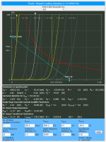
Since I purchased SE cad and don't know how to use it just put some data in it and got these result. At 15K software warns too high of plate impedance . Attached comparison data for you all experts to review. Can some one help me with the parameter Vin. What will be a nominal input voltage for 845 tube or how do you get it?
Looks like the Vin is the peak input voltage. The max input voltage you can apply in Class A1 (i.e. without entering the region where the grid becomes positive respect to the cathode) is the bias voltage.
However this comparsion is not representative of the actual amplifier because the Rdc and the nominal primary impedance don't tell much about the final performance. That's just the average tube distortion into a resistive load. Might be representative for midrange only.
Even so if you reduce the input voltage for the 7.5K load to match 7.5W ouput of the 15K load, distortion will decrease. Then if you adjust the quiscent condition for the 7.5K to a more convenient 900V/90V the difference will be even less and max output power still more than 15K case. Then, being dominant 2nd order, you can cancel it out with the driver 2nd order and get even better results!
In real amplifiers such differences will be pretty much irrelevant if the speakers are right. For example, those differences in STATIC (or small signal) damping factors are too small to make any real difference. If the speaker is right they will all be ok if the speaker is wrong none of them will be appropriate. The are pretty much the same from a practical point of view.
Valve amplifiers need dedicated speakers so that the bass alignment is correct (i.e. it takes into account actual output impedance) and speaker impedance should be as close as possible to a flat resistive value.
The reason why commercial manifacturers went with ultralow output impedance a long time ago and insist about its magic powers is that this way speakers and amplifiers can be designed separately making life easier and things cheaper with more income.....
They are equivalent. The 845 is low mu with lower plate impedance. These tubes, unlike most, display low distortion working on relatively low loads until they approach cutt off. For this reason load impedance makes less difference. The 211 has 2-2.5 times higher plate impedance and so typically will require higher primary load to get similar results.
People draw too many load lines that in reality don't happen and jump to conclusion.
Agree, but in datasheet and simulations the 211 seems to be a bit more linear than the 845, assuming the same load.
Unfortunately I cannot use them because of the transformer. 🙄
Agree, but in datasheet and simulations the 211 seems to be a bit more linear than the 845, assuming the same load.
Unfortunately I cannot use them because of the transformer. 🙄
Curves on datasheets are anything but accurate. Simulations get close only if taken from actual curves with actual components. But still the amplifier distortion is another story which depends on the tube and everything around it. In the end it's about splitting hairs. No practical difference there.
http://www.lundahl.se/wp-content/uploads/datasheets/1688.pdf http://www.lundahl.se/wp-content/uploads/datasheets/1691.pdf 350€
In class A tube can take 75w max
In class A tube can take 75w max
Attachments
http://www.lundahl.se/wp-content/uploads/datasheets/1688.pdf http://www.lundahl.se/wp-content/uploads/datasheets/1691.pdf 350€
In class A tube can take 75w max
75W was the spec before 1939. Then it became 100W.
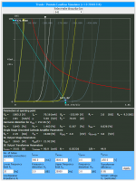
Why you all insist in comparing very different primary loads with same plate voltage and same anode current? If it is optimal for one it will not be for the other....or compormised for both....
Anyway I can see that with 9K you get over 18W (loss included, I guess) and in the other case it doesn't do more than 11.5. You should also show what happens when the ouput power is the same at 11.5W.
Lundahl datasheets also show that the 9K transformer has 75H and the 20K has 70H! At low frequency there is no question that 9K will be far better....
Let's not talk about high frequency I have been quite disapponited with Lundahls recently.....
45 what happens at 12K primary impedence with frequency?
Is the the transformers impedence that limit the power out put?
Is the the transformers impedence that limit the power out put?
45 what happens at 12K primary impedence with frequency?
Is the the transformers impedence that limit the power out put?
Not so different from 10K. There is no written limit, it's more a matter of balance of all aspects.
Also exaggerating with the primary load plate efficiency becomes really low.
What if I go down to plate voltage of 800V?
What is the maximum power I can get from 845 tube?
In class A1, at 800V/90mA into 5K around 17-18W. As usual, depends on the quality of the tubes, transformer losses etc. If you buy Chinese 845's only premium tubes will get you there.
It has to be 5K. 45, can you please educate as how to calculate these values?
Get the datasheet, take the curves and draw the loadline. This will give an estimate at medium frequencies.
To get the loadline you need two points. The line equation is V=-RLoadI+V0.
You already have one point (i.e. anode current and voltage in quiscent conditions) so you only need another point which you can calculate from the equation above. Calculate V0 in the equation above: V0=RLoadIa+Va where Ia and Va are the anode and plate voltage you want to use.
Now that you know V0 you can use as second point the intercept with the voltage axis. Set I=0 in the original equation and this is precisely V0!
In summary you need two points (Va;Ia) and (V0;0). Once you have them draw the line across the full plane.
Then you apply a symmetric voltage swing respect to the quiescent point and see where the loadline intercepts the tube curves with the applied grid voltage. For example, you have -100V bias. Then you apply +/-100V. You need to find where the line intersecs the tube curves correponding to grid voltages equal to 0 and -200V. These two new points will give max and min voltage and max and min current. The RMS power is Pout=[(Vmax-Vmin)*(Imax-Imin)]/8000
The factor 8000 comes from the fact that voltage is in volts and currents are in mA (so you need to turn the current into A) and are using peak-to-peak values for both voltage and current (the need to be converted in RMS). The factor 8 is indeed two times 2*SQRT(2).
If you don't know these things I suggest you first learn with simpler and less dangeours amplifiers....
Of course the final decision is yours.
Sure, I bet on that.
there must be, otherwise, i will just get the H50 grade, cheapest and lowest quality and be done with it.....
although truth to tell, i use the H50 in my guitar amp builds exclusively, otherwise for hifi amps, it is z11 or rm18, with lams 0.35mm thick...while the H50 are 0.5mm thick...
Curves on datasheets are anything but accurate. Simulations get close only if taken from actual curves with actual components. But still the amplifier distortion is another story which depends on the tube and everything around it. In the end it's about splitting hairs. No practical difference there.
statistics, based on a large sample of tubes, and is a bell curve, so most likely
tube samples on top of the bell were used to make the plate curves....
@Kinku, download yourself any of these RCA tube manuals, if the early pages, there are good explanations that you can learn from...http://www.tubebooks.org/tubedata/RC30.pdf
Can some one help me with the parameter Vin. What will be a nominal input voltage for 845 tube or how do you get it?
Vin is your af input signal, reading tubelab's postings, the 845 it seems started drawing grid current even before the grid bias hits 0 volts, in the chinese tubes he tested.
notice that with a fixed bias of -131 volts, plate current was 80mA, this is the operating point, or bias at idle...
the driver tube then has to deliver 100 volts peak of af input signal,
so that means a higher plate voltage for the driver tube...
how to get this is a subject for another thread imho...
look at several designs of 845 amps and you will know what i mean...
@kinku, BudP, cerrem, YvesM are the traffo gurus here, sorry if i missed out some...
you can search for their postings and learn from the masters...
you can search for their postings and learn from the masters...
statistics, based on a large sample of tubes, and is a bell curve, so most likely
tube samples on top of the bell were used to make the plate curves....
I am pretty sure of what say for the simple fact that I built the amplifier working at 800V/90mA with 5K some 10 years ago...when I had plenty of time!
 The bias was about -106-107V. DC heating of course. The amplifier had 17W output power @ 2%THD (just over 18W at the primary).
 If you get the loadline from the RCA data sheet (with DC heating) you will get about the same power but 5-6% 2nd harmonic distortion already. This happens because it is not very accurate and because the driver in my amp was cancelling some 2nd harmonic. Even so 2nd harmonic was still several dB's above the 3rd then a tiny 4th harmonic peak and finally nothing else. I still have the notes of those measurements. Without cancellation THD was about 3.5%. Better than datasheet estimate.....
Tubes were selected Chinese Golden Dragon brand and the transfomer my design with rather low copper loss.
there must be, otherwise, i will just get the H50 grade, cheapest and lowest quality and be done with it.....
although truth to tell, i use the H50 in my guitar amp builds exclusively, otherwise for hifi amps, it is z11 or rm18, with lams 0.35mm thick...while the H50 are 0.5mm thick...
In a SE transformer the effective magnetic permeability is a design choice, not a lamination's manufacturer caprice, trust me.
The main requirement for the lamination is its losses, does not matters its magnetic permeability, up to some degree, do not use "sardine can" by the way.
No problem if you use NOSS, as long as it is low losses.
Push-pull transformers are a totally different matter.
In a SE transformer the effective magnetic permeability is a design choice, not a lamination's manufacturer caprice, trust me.
pieter t, what say you?
@kinku, BudP, cerrem, YvesM are the traffo gurus here, sorry if i missed out some...
you can search for their postings and learn from the masters...
pieter t, what say you?In a SE transformer the effective magnetic permeability is a design choice, not a lamination's manufacturer caprice, trust me.
First you ignore him, and now you want that he wake up at 4:00AM...😛😀
Last edited:
- Home
- Amplifiers
- Tubes / Valves
- OPT for 845 tube