I am planning to use between 900-1000V. I am not sure where this discussion is going. Can anyone recommend a transformer impedence that works with it and deliver close to 15-20 watts? I downloaded SE cad from glassware but need to read how it is done.
Jazbo can you please explain why you picked Rk=0 Rt=198
Jazbo can you please explain why you picked Rk=0 Rt=198
I am planning to use between 900-1000V. I am not sure where this discussion is going. Can anyone recommend a transformer impedence that works with it and deliver close to 15-20 watts? I downloaded SE cad from glassware but need to read how it is done.
Jazbo can you please explain why you picked Rk=0 Rt=198
900V/90mA resulting in a bias at about -130V should give a max Pout around 20-22W with 5-6K. For 15W you can go down to about 800V with 5K.
In reality with 1000V and 10K you should be able to get about 20W as well but more drive is required.
So it's more important that you build the power supply or estimate accurately what you you will get and find the best deal in 5-10K range.
Higher primary impedance than 10K with the 845 is not a good idea for me.
More than power I am looking for lower distortion. The reasoning behind using or not using 16K is not for power but to make it more linear. why do you think going to 16K is an issue?
More than power I am looking for lower distortion. The reasoning behind using or not using 16K is not for power but to make it more linear. why do you think going to 16K is an issue?
A 16K transformer that has to work with high voltages and at relatively high power is very expensive if done properly. Poor inductance will result in higher distortion already @100Hz at intermediate power level. Getting enough inductance means that it will require a more complicated geometry to achieve the same high frequency behaviour.
The 845 is linear enough to run fine with 5-10K. Distortion will be quite low up to 60-70% of nominal power anyway if you buy good 845's. With 16K might be a bit lower if you can get a good enough transformer but will also clip harder. Not worth for me.
I didn't mean to sound dogmatic - all of these loading decisions are judgement calls. In the old days, and still for commercial designs, every last measurable watt must be extracted and Devil take the hindmost.
DIY designs can be optimized for other things, including linearity and speaker damping, and a dB or two peak output can be traded against that. In that context the optimum load for a type 2A3 would be 4000 or 5000 Ohms reflected, for example.
And these are just pretend numbers anyway; speakers are not resistive and also not 8 Ohms. The amplifier needs enough cushion to operate into a reactive load and a generally messy one at that!
All good fortune,
Chris
thanks for confirming what i suspected all along....this is all i want to know...
Winding ratio would be the same.
But what to do with primary inductance??
211 approaches 4k Rp.....
I have been working on a ~ 16k OPT for 211; this is territory where you meet the limits....
It is not strange that there are no commercial offerings for 211 OPT's with ~ 16k primary impedance.
the iron core is good up to about 400hz isn't it?
inductance is a function of core quality too...
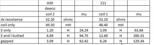
i have done comparison of the m6/z11 versus the H50
cores as used on small chokes, and found out that permeability
is three times more in favor of m6/z11...
Conclusion: The same turns ratio does not mean equivalent transformers.
who said they are?
i have done a lot of them and i know what works and how good they work,
but this is just me....i am not math savvy to prove anything....
just that i make traffos and use them in my amps...
the iron core is good up to about 400hz isn't it?
inductance is a function of core quality too...
i have done comparison of the m6/z11 versus the H50
cores as used on small chokes, and found out that permeability
is three times more in favor of m6/z11...
Yes.
The better core materials have higher permeability, but in general also lower maximum B, so that's another compromise to fight 😱
Amorphous has less permeability than (good quality) M6, but less core loss and less eddy current because of the very thin tape.
Finemet (nanocrystalline) has at least as good permeability as M6, and very little loss / eddy current (best of both worlds).
However, maximum B gets lower for these high quality materials: amorphous 1.56T; finemet 1.25T, whereas HiB silicon steel can reach over 2T.
For good quality transformers stay well below 1T anyway.
inductance is a function of core quality too...
In a well designed and properly wound SE transformer this is not strictly true.
Primary inductance is given by
Lp = (4 π μeff S Np²) / (9 l x 10⁸)
And
μeff = lm μ / (lm + lgap μ)
The most common lamination used here is called EI155, its magnetic circuit length is
lm = 22.8 cm
For an air gap of 0.25 mm
lgap = 0.05 cm
For a standard M6 lamination, sorry only 4 points in EDCOR web page
For a super duper Japanese low loss lamination, sorry I do not remember its code name, just google Nippon Steel & Sumitomo Metal.
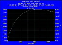
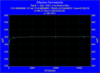
Doing calculations, for the core with standard M6 lamination
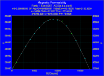
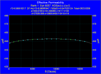
Doing calculations for the core with Japanese lamination
Having into account the DC magnetic field, say about BDC=5000 Gauss, in the range of 5000 Gauss up to 12500 Gauss, for standard M6 core is
μeff ≈ 452
For the core with Japanese lamination
μeff ≈ 452
Surprise surprise, magnetic permeability and hence primary inductance is almost the same, regardless core "quality" 😉
Attachments
Last edited:
I like to have a discussion on core materials too. So there is no difference in quality as long as it is well made?
I came across this earlier discussion . Bud Purvine from o-netics explains
http://www.diyaudio.com/forums/tubes-valves/150034-output-transformer-silicon-steel-amorphous.html
Can we please focus on output transformer primary coil impedence for 845's OPT.
So it seems like 10K is the way to go.
I downloaded the SE Cad program but don't know how to use it.
So the requirement for transformer makers are
Primary impedence
Current requirement
Power rating for OPT
Secondary impedence
��
Last edited:
I like to have a discussion on core materials too. So there is no difference in quality as long as it is well made?
I did not say that, I did say that primary inductance is almost the same, regardless core "quality", if for somebody quality means high magnetic permeability.
Nevertheless you must exclude e.g. a core made of "sardine can"
The air gap in a SE transformer is a great equalizer, so you must pay attention on core losses, they must be as low as possible, because they are related to transformer linearity.
So it seems like 10K is the way to go.
As I said before, a 16K transformer is a nightmare to design and build, so 10K is reasonable, the 845 is not as linear as the 211, so probably you do not hear the difference between 10K and 16K, maybe a proper circuit is more important.
That chart is just an example to show the load line (see Tubelab's site), which may or may not meet your design goals.Jazbo can you please explain why you picked Rk=0 Rt=198
I did not say that, I did say that primary inductance is almost the same, regardless core "quality", if for somebody quality means high magnetic permeability.
this is an actual comparative testing i did comparing M6/z11 tp h50 irons...
quality of the core matters, all else being equal....
Attachments
-
 11046721_908391689182466_6105049192211106634_n.jpg79.3 KB · Views: 114
 -
 11034280_908391432515825_6692404252934355827_n.jpg75.8 KB · Views: 109
 -
 10995680_908391352515833_3617309621963891442_n.jpg81.2 KB · Views: 125
 -
 10647139_908391785849123_8056372604479773786_n.jpg88.8 KB · Views: 134
 -
 10334404_908391155849186_2426223067974673256_n.jpg18.7 KB · Views: 115
this is an actual comparative testing i did comparing M6/z11 tp h50 irons...
quality of the core matters, all else being equal....
i) We are talking about SE transformers, not chokes, so a proper measurement wil be done with...er...a SE transformer.
ii) Primary inductance must be measured with both DC and low frequency AC flow, at transformer specs.
If you are measuring inductance with an LCR meter at high frequency, without the DC component, the AC magnetic field will be too low because
Bac = (Uac x 10⁸) / (√2 π f S Np)
Frequency is in the denominator, so if it is high, the magnetic field will be too low.
In the numerator you has the primary voltage, usually in the order of hundreds volts, but I just can see a 9V battery, then the magnetic field will be even lower.
At such lower magnetic field you are measuring into a region with huge differences in magnetic permeability, and the air gap does not equalizing it anymore.
Conclusion: You are comparing apples with oranges, and with all due respect your measurements are very poorly made, even it can be seen a photo with the value L=331mH which is not tabulated.
Hint: Do a proper measurement, with a SE transformer, at say Bac=Bdc=5000Gauss, with a lower frequency (50Hz/60Hz is fine) and the rated primary voltage, then you would compare apples with apples. 🙄
Last edited:
i was comparing a low quality iron with a good quality iron,
no matter how flawed my method was, it showed a difference...
and that is all that mattered to me....
no matter how flawed my method was, it showed a difference...
and that is all that mattered to me....
no matter how flawed my method was, it showed a difference...
and that is all that mattered to me....
Sure, I bet on that.
They are equivalent. The 845 is low mu with lower plate impedance. These tubes, unlike most, display low distortion working on relatively low loads until they approach cutt off. For this reason load impedance makes less difference. The 211 has 2-2.5 times higher plate impedance and so typically will require higher primary load to get similar results.the 845 is not as linear as the 211,
People draw too many load lines that in reality don't happen and jump to conclusion.
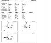
some data
Since I purchased SE cad and don't know how to use it just put some data in it and got these result. At 15K software warns too high of plate impedance . Attached comparison data for you all experts to review. Can some one help me with the parameter Vin. What will be a nominal input voltage for 845 tube or how do you get it?
Since I purchased SE cad and don't know how to use it just put some data in it and got these result. At 15K software warns too high of plate impedance . Attached comparison data for you all experts to review. Can some one help me with the parameter Vin. What will be a nominal input voltage for 845 tube or how do you get it?
Attachments
- Home
- Amplifiers
- Tubes / Valves
- OPT for 845 tube