Thanks for the detailed reply...
I did not mean to keep with the questions.
What I was trying to ask and I think you answered my question is if those 4 caps in that location were the 4 post dac caps you refer to and if the same low esr caps are recommended pre and post cap.
Thanks again for all tje insite...
I will try these and see what results I get
Well... No. These 4 original caps one can see in the regulator area are not the same I refer to (large decoupling capacities). These decoupling caps it should be attached in one way as close as possible to the DAC chip AVCC pins, while the AVCC regulator it may be as it is (untouched). To add some extra decoupling caps, one do not need to modify anything at the AVCC regulator.
Ok... claro.
I think I will concentrate on the pre dac for the moment...
I am not brave enough yet to solder directly on the dac...
That will have wait a bit
Thx
I think I will concentrate on the pre dac for the moment...
I am not brave enough yet to solder directly on the dac...
That will have wait a bit
Thx
I have published a picture in post 960, where is wrong indicated a 5v point as Standby rail.
Unfortunately I can not correct directly on that picture.
So, I may do the correction by this post here. The 5v point to be seen in post 960 is the 5v rail of the player (105). The 5v Standby is to be found inside the SMPU.
Unfortunately I can not correct directly on that picture.
So, I may do the correction by this post here. The 5v point to be seen in post 960 is the 5v rail of the player (105). The 5v Standby is to be found inside the SMPU.
Well, well... I`m glad to announce full success with the divider board (last edition/version) testing.
Connected in place in a 105 model. Even though I still have in my player, a post DAC processing circuit which is in a prototype stage, the improvements in both sounds and picture are dramatic after connecting this clock board...
I`m very proud to tell you that my BDP 105 player sounds now much better than the last Oppo high quality device HA-1.
I will come back soon with more details.
Attachments
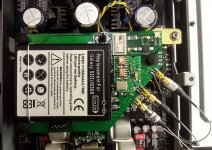
This is the Clock divider in its last version, doing a good job together with the battery powered clock board (pictured above).
One concept this mod is based on: using a high frequency main oscillator, and then divide the frequency to the necessary clock frequencies.
In this case, of 105/105D models, we may need mainly to clock the DAC chip and the processor of the machine. Fortunately, the clock frequencies these two components need it can be arranged to be multiple in between. Here it comes another concept this mod is based on: synchronism of the clock signals (best) for the whole system.
In the particular case of 105 model player, the clock frequency for QDEO chip is not multiple of the other two frequencies, so one may use a standalone oscillator (20Mhz) dedicated to this chip (but powered from the same battery). For the 105D model this problem is solved by Oppo designers, who found already an 27Mhz clock for the HDMI chip. Therefore, this divider mod board it works/fit perfectly for this model (with two perfect synced 27Mhz outputs and one 108Mhz for DACs).
The third concept about this mod is to be used a noise free battery power for all the clocks oscillators in the system.
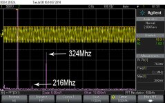
What it may be the clue to have a higher frequency oscillator than the needed clock frequency? Well, there is a known fact that as higher the frequency of an oscillator it is made for, the better its figures/parameters, stability, and so on. So, I decided to use a 216Mhz oscillator. I could go even higher, but then it may apear problems about the PCB design and its material, and so on. I think this 216Mhz is in this case a good compromise.
The divider chips introduce some errors in the circuit, but there is however a benefit when starting from a higher quality clock signal. The overall errors are minimized in such case, than when starting from an already lower quality main clock signal.
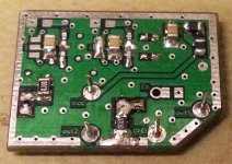
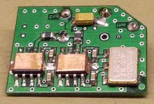
It is used in this case a (custom produced) SAW oscillator of 216Mhz, divided further by 2 and by 8 by two chip specified to work in Ghz frequency range, all mounted on a 4 layers design small PCB. For improved performances, the divider chips are individually shielded, but a shielding of the whole divider PCB it may be desired too. I will also recommend shielding of the battery.
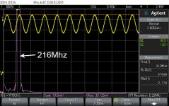
I publish here two snapshots of the two SAW oscillator, one 108Mhz and another 216Mhz.
As you can see, the 216Mhz oscillator is damn good. It perform better than 108Mhz and is specified at least for a phase nose of 0,21ps for this frequency.
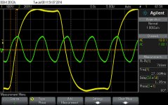
What about the errors introduced by the divider chips? The main error here is the delay. As you may see in the pic attached here, the delay between 108Mhz and the 27Mhz frequency at the dividers output is 1,95ns, and a shift phase of 80 dg.
The delay in such configuration is unavoidable, but this error is not important in this particular case. Originally, the main components of the system it have each its own oscillator. These are completely out of synchronism. As the data have to be synchronized, special circuits have to work to fix this problem. Errors occur, which have to be corrected. Such functioning mean time and resources needed from the whole system to fix eventual problems, instead of going straight forward to output the signals. What about heaving the same (and very stable) error all the time to be corrected? Like a delay error of 1,95ns? The system do not have to synchronize different clock/bit frequencies, but correct only a delay problem. In my opinion, this is beneficial for the system functionality, and the results confirm at least well this way of thinking.
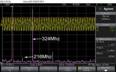
There is a little inconvenient when using this divider type chip. It have a quite low-level output. A low level it fit just fine the processor need (and HDMI chip for 105D model), but it may be too low for Sabre chip. Well this “inconvenient” it can be very well turned into a benefit… As you may see in the screenshots here, there is a harmonic of 324Mhz which is quite high in level. For a high-level clock output frequency, this harmonic level is even more important. It goes into/through the trigger circuit of the DAC chip. When about a low-level clock signal, this harmonic is low itself too. The trigger window of the ES9018 is very tight. The chance that this harmonic do not reach the trigger level (or go in further) increase dramatic with a low level clock signal. The trigger level it can be adjustable at the ES9018 clock input pin…
A work around to make the DAC chip to work with a low-level clock signal it will be provided (as installation guide) to those who will want to implement this mod.
And something quite important for those who will think to mod in the clock area of Oppo players (or in general). In my opinion is much better to deliver the clock signals to the targeted circuit, without its DC component. In this case, AC/DC separation is made by a particular way of connection inside the MMCX connectors. Otherwise, the Divider board does not provide AC/DC isolation.
Some words about the control signal for ON/OFF clock on the battery board.
This board need the presence of a 5v or 12v tension to know when to start the oscillators.
The SMPS of the player deliver 5v continuous as long it is connected to the wall. This power keep active some standby circuits in the player. A such circuit is the one which control the main power relay. There is a 15v DC, which feed a 12v relay… Well, this is the choice of the Oppo designers. I can guess why they chosen so, but this it may be another discussion…
The point here is that one may use this 15vDC to activate the battery powered clock board. The main advantage to use this tension is that the clock start and stop exactly in the same time with the whole system. A work around about this it will be provided.
Another alternative to control the clock board is to use the 5v DC rail of the player, which is ON only when the player is turned ON. If one will improve the filtering of this 5v rail (very recommended), then this rail it may be up few seconds longer time after the player is switched OFF. If this 5v rail controls the clock board, then the clock signals it may be active long time after the player is turned off. Well nothing wrong it happen (I used my player so quite long time), but this way it may not be a very professional way to do it.
Therefore, my recommendation is to be used the 15v control tension available in the player SMPS.
The clock board it can be equipped with a 12v or 5v relay, as one may want, but this aspect it may be clarified in each case of implementing this mod (for those interested).
A note to conclude this long post.
My oscilloscope it have a 200Mhz bandwidth. Therefore, I cannot know if the 108Mhz clock signal is a square signal one, but after the FFT calculation I suppose it may be a sine signal. In theory, it should result a square signal out of the divider chip…
The 216Mhz (is for sure a very fine sine one at the oscillator output pin) and 108Mhz signals at the divider chip output pin looks very similar as sine… What in fact the shape of this 108Mhz clock signal is it still be unclear for the time being.
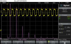
The FFT calculation in the case of the square 27Mhz clock signal is irrelevant, but is there in the picture…
One concept this mod is based on: using a high frequency main oscillator, and then divide the frequency to the necessary clock frequencies.
In this case, of 105/105D models, we may need mainly to clock the DAC chip and the processor of the machine. Fortunately, the clock frequencies these two components need it can be arranged to be multiple in between. Here it comes another concept this mod is based on: synchronism of the clock signals (best) for the whole system.
In the particular case of 105 model player, the clock frequency for QDEO chip is not multiple of the other two frequencies, so one may use a standalone oscillator (20Mhz) dedicated to this chip (but powered from the same battery). For the 105D model this problem is solved by Oppo designers, who found already an 27Mhz clock for the HDMI chip. Therefore, this divider mod board it works/fit perfectly for this model (with two perfect synced 27Mhz outputs and one 108Mhz for DACs).
The third concept about this mod is to be used a noise free battery power for all the clocks oscillators in the system.
What it may be the clue to have a higher frequency oscillator than the needed clock frequency? Well, there is a known fact that as higher the frequency of an oscillator it is made for, the better its figures/parameters, stability, and so on. So, I decided to use a 216Mhz oscillator. I could go even higher, but then it may apear problems about the PCB design and its material, and so on. I think this 216Mhz is in this case a good compromise.
The divider chips introduce some errors in the circuit, but there is however a benefit when starting from a higher quality clock signal. The overall errors are minimized in such case, than when starting from an already lower quality main clock signal.
It is used in this case a (custom produced) SAW oscillator of 216Mhz, divided further by 2 and by 8 by two chip specified to work in Ghz frequency range, all mounted on a 4 layers design small PCB. For improved performances, the divider chips are individually shielded, but a shielding of the whole divider PCB it may be desired too. I will also recommend shielding of the battery.
I publish here two snapshots of the two SAW oscillator, one 108Mhz and another 216Mhz.
As you can see, the 216Mhz oscillator is damn good. It perform better than 108Mhz and is specified at least for a phase nose of 0,21ps for this frequency.
What about the errors introduced by the divider chips? The main error here is the delay. As you may see in the pic attached here, the delay between 108Mhz and the 27Mhz frequency at the dividers output is 1,95ns, and a shift phase of 80 dg.
The delay in such configuration is unavoidable, but this error is not important in this particular case. Originally, the main components of the system it have each its own oscillator. These are completely out of synchronism. As the data have to be synchronized, special circuits have to work to fix this problem. Errors occur, which have to be corrected. Such functioning mean time and resources needed from the whole system to fix eventual problems, instead of going straight forward to output the signals. What about heaving the same (and very stable) error all the time to be corrected? Like a delay error of 1,95ns? The system do not have to synchronize different clock/bit frequencies, but correct only a delay problem. In my opinion, this is beneficial for the system functionality, and the results confirm at least well this way of thinking.
There is a little inconvenient when using this divider type chip. It have a quite low-level output. A low level it fit just fine the processor need (and HDMI chip for 105D model), but it may be too low for Sabre chip. Well this “inconvenient” it can be very well turned into a benefit… As you may see in the screenshots here, there is a harmonic of 324Mhz which is quite high in level. For a high-level clock output frequency, this harmonic level is even more important. It goes into/through the trigger circuit of the DAC chip. When about a low-level clock signal, this harmonic is low itself too. The trigger window of the ES9018 is very tight. The chance that this harmonic do not reach the trigger level (or go in further) increase dramatic with a low level clock signal. The trigger level it can be adjustable at the ES9018 clock input pin…
A work around to make the DAC chip to work with a low-level clock signal it will be provided (as installation guide) to those who will want to implement this mod.
And something quite important for those who will think to mod in the clock area of Oppo players (or in general). In my opinion is much better to deliver the clock signals to the targeted circuit, without its DC component. In this case, AC/DC separation is made by a particular way of connection inside the MMCX connectors. Otherwise, the Divider board does not provide AC/DC isolation.
Some words about the control signal for ON/OFF clock on the battery board.
This board need the presence of a 5v or 12v tension to know when to start the oscillators.
The SMPS of the player deliver 5v continuous as long it is connected to the wall. This power keep active some standby circuits in the player. A such circuit is the one which control the main power relay. There is a 15v DC, which feed a 12v relay… Well, this is the choice of the Oppo designers. I can guess why they chosen so, but this it may be another discussion…
The point here is that one may use this 15vDC to activate the battery powered clock board. The main advantage to use this tension is that the clock start and stop exactly in the same time with the whole system. A work around about this it will be provided.
Another alternative to control the clock board is to use the 5v DC rail of the player, which is ON only when the player is turned ON. If one will improve the filtering of this 5v rail (very recommended), then this rail it may be up few seconds longer time after the player is switched OFF. If this 5v rail controls the clock board, then the clock signals it may be active long time after the player is turned off. Well nothing wrong it happen (I used my player so quite long time), but this way it may not be a very professional way to do it.
Therefore, my recommendation is to be used the 15v control tension available in the player SMPS.
The clock board it can be equipped with a 12v or 5v relay, as one may want, but this aspect it may be clarified in each case of implementing this mod (for those interested).
A note to conclude this long post.
My oscilloscope it have a 200Mhz bandwidth. Therefore, I cannot know if the 108Mhz clock signal is a square signal one, but after the FFT calculation I suppose it may be a sine signal. In theory, it should result a square signal out of the divider chip…
The 216Mhz (is for sure a very fine sine one at the oscillator output pin) and 108Mhz signals at the divider chip output pin looks very similar as sine… What in fact the shape of this 108Mhz clock signal is it still be unclear for the time being.
The FFT calculation in the case of the square 27Mhz clock signal is irrelevant, but is there in the picture…
Attachments
-
 Clock delay108Mhz-27Mhz.jpg162.1 KB · Views: 130
 -
 27Mhz - Divider output.jpg161.7 KB · Views: 126
 -
 108Mhz- Divider output.jpg179.8 KB · Views: 137
 -
 216Mhz main osc.jpg160.2 KB · Views: 452
 -
 108Mhz main osc.jpg201 KB · Views: 469
 -
 ClockDividerB.jpg308.5 KB · Views: 485
 -
 ClockDivider.jpg275.3 KB · Views: 509
Last edited:
BTW, the Divider board is quite flexible when about areas of applications/use. It is soldered by hand and it can of course be customized for another kind of divider tasks, using another oscillator frequencies, and/or it can be set it up for different divider factors (2, 4, 8, 10).
Last edited:
And a little detail more...
After I have finished assembling this divider, I have experimented first with a clock board equipped with the 3 oscillators for my 105 model: 108 Mhz SAW oscillator for DAC, 20Mhz good quality one for QDEO chip, and a good quality 27Mhz oscillator for processor. The same original clock configuration, except the higher frequency for DACs, and powered all together from battery. Then I have mounted the clock board with the divider on it (216Mhz osc. with differential output). I have not tried yet with the SAW 108Mhz as main clock for divider...
The difference was/is very obvious in the favour of the divider configuration. I may say quite spectacular.
Last edited:
...216Mhz osc. with differential output). I have not tried yet with the SAW 108Mhz as main clock for divider...
The difference was/is very obvious in the favour of the divider configuration. I may say quite spectacular.
Hi Coris
Maybe I have missed it, but two things, is the 216MHz SAW available off the shelf or did you have to order that value. Also, what is the divider chip you ended up using, to get 108MHz and 27MHz?
Feeding higher than 100MHz to the Sabre DAC in the Oppo '95 was prone to funny misbehaviour, especially if you didn't diable the multi-channel, but the '105 is much better in that regard and tighter layout for the Stereo Sabre DAC, but I have not used anything above the maximum 100MHz in the '105 as recommended by ESS, but you have tried it with 108MHz and also left the multi-channel functioning (via the clock driver IC), right?
Cheers, Joe
Hi Joe
There are not produced oscillators for exactly 216Mhz. Nobody (producer) have interest to produce such. I do not know why. There is no application for such frequency, I may suppose. At least nobody use (yet) SAWs for consumer marked applications... One may order that value, for a quite consistent batch... Not a cheap business...
I had never problems with higher clock frequencies for Sabre chip, either for 95 or 105 model.
The only explanation I can think (when you state about problems) is that I have made some more improvements in the rest of the circuits, than you did... Absolute any problem, but highly improved sound, up to 125Mhz clock. The misbehaviours started for me at around 127Mhz clock... The frequency difference from 100 to 108 is just minimal for ES9018, which run well at even higher clocking. You may only try/test it.
At least you can use any kind of oscillator around 108Mhz to test the Sabre chip. If you need just a SAW, I can sell you an 108Mhz osc.
The differential clock drivers for multichannel stage are both specified up to 200Mhz. So it works well at anything into this range. I have tested this, but the multichannel board is removed from my system, as I`m not interested in this kind of sound system. I can not see any reason the multichannel board should not work with 108Mhz clock. At least is the same chip in the same configuration, except the channels distribution.
When about funny thing, I can say that I found something (negative) when about the caps over the Sabre chip differential output. I will come back to this after I will have more infos. It worked for me just fine this trick when I used PCM1792 DAC...
Last edited:
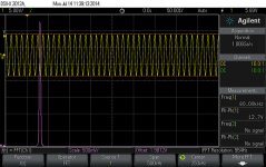
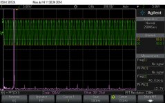
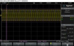
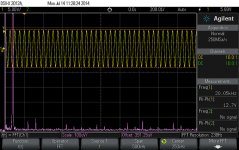
I think to show you how it looks some test signals through the player in this configuration, with battery powered (unified) clock.
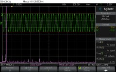
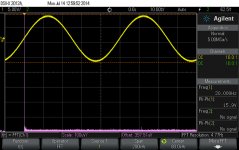
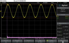
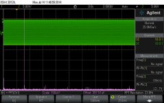
I have generated digital files of 10Hz, 20Hz, 20Khz, 40Khz, and 80Khz sine wave. The signals 10/20Hz are -1dB amplitude, while the rest are -3dB amplitude. My fault because the different amplitudes...
The files were played as usual from a USB stick. The channels output is connected directly to the scope`s channels (identical probes).
I some pics are shown the FFT signal real amplitude (4v) for the given test signal. This is the same for all test signals (except 10/20Hz which are -1dB amplitude - these shows 5v FFT amplitude)
As you can see, the output amplitude is quite constant for the whole frequency range (12,7 Vpp, except for the 10/20Hz which are 2dB higher level).
The screen shots looks similar for both stereo channels. (I had to cut out some pics to not exceed the 10 files attachments limit for this post).
Some harmonics are to be seen as out of audible range and under 100µV level, for a 4v level of the main frequency. I appreciate this as just as exceptional!
Please note that my actual post DAC processing circuit (I/V & final) is in a prototype stage (not quite perfect...), and I still use the players`s regulators, but with improved filtering for the whole power system.
Attachments
-
 80Khz -signal amplitude.jpg229.2 KB · Views: 77
 -
 40Khz - LEFT.jpg243.2 KB · Views: 81
 -
 40Khz -signal amplitude.jpg227.3 KB · Views: 78
 -
 20Khz - RIGHT.jpg239.6 KB · Views: 77
 -
 20Khz - LEFT.jpg240.8 KB · Views: 388
 -
 20Hz - LEFT.jpg179.3 KB · Views: 396
 -
 20Hz -signal amplitude.jpg176.3 KB · Views: 395
 -
 10Hz - LEFT.jpg191.2 KB · Views: 404
 -
 10Hz -signal amplitude.jpg181.9 KB · Views: 404
 -
 80Khz - LEFT.jpg231.3 KB · Views: 82
Last edited:
Some more infos about battery capacity.
As you can see, the battery capacity for this device is 2300mA/h. The divider PCB is using 57mA. If a second oscillator is needed (in case of 105 model), then the total current may increase to 70-80 mA (depends on second oscillator type). This is in fact the current needed for the board I used for tests.
The battery fully charged it have 4,2v (at the oscillator pins measured 3,6v). I have run it a fully charged battery on my board for a total of 24 hours, until the DAC become unstable (low level clock signal). This happened at 2,96v for battery, and 2,65v at the oscillator power pins.
These measurements shows very well that the oscillator chips it have built in a very efficient regulator... At least oscillators do not need regulators to regulate the voltage at its power pin. The regulators are only needed to lower (filter out) the noises coming through power rails... A voltage variation (of a whatsoever frequency or pulses) at the oscillator power pin, it can be defined as noise. The discharged rate of a battery it not look at all as noises... This detail (differentiation) it may be quite important.
In all this battery discharging time I could never detect any whatsoever changing in sound quality at the player outputs. I was just surprised when I heard suddenly hicks up in audio signal, because too low level clock signal. There was the only behaviour which told me that the battery is too low. The same constant excellent sound quality all the time.
I can say that I`m quite impress myself by the way it works this clocking device integrated in the player system...
PreDAC caps again...
Hi Coris,
Really good work on the clock...
Wrt the preDAC caps, I ended up installing 4 Nichicon CG Aluminum Organic Polymer Capacitors 6.3V 2700uF for the higher capacitance as suggested...
These are SMD types and larger than the original caps so installation had to be creative. I chose them over the Nichcon HZ due to their lower esr and higher ripple current.
After 2 days burn in, they have added another level of richness to the sound of the sound. Instruments sound more complete now and the continuity between the base lines and the higher registers is smoother.
Thanks for the suggestion... very worth while.
....Using low ESR caps for decoupling purposes is a must. The decoupling caps are in a way in audio signal path. Indirectly. The caps used for decoupling may not be very appropriate for directly use in audio signal path (filtering, signal separation), or it may "sounds" different. So one may use the appropriate components for the right place in a circuit. Also experimenting is a good way to get results...
Best is in my opinion, to not use caps at all directly in audio signal path, but decoupling accordingly some of the circuits involved in audio signal process, it have quite important impact for the signal quality.
Coris,
These clock experiments are very interesting.
However, there would be more useful for others if you generated full scale signals. This would make it easier to hook them into the boards.
Also, I wonder about the need for a battery supply. Now that everything is working well, perhaps you could compare to a more traditional LC filtered regulated supply from the existing voltage sources in the box.
Also, we would be interested to hear about your IV stage.
Eric
Hi Eric
Thanks for your appreciations.
I`m not very sure if I understood what you mean with "generated full scale signals".
Actually there is not here about experiments, but just a functional stable modification...
The meaning of this project is to provide a cleaner power supply to a sensitive device as oscillators used for clocking a digital system. The other meaning is to have all these clocks working in a synchronised manner. This last task is partial realized, when about BDP105...
Also there is very easy to connect this board with its clock outputs to the rest of the system. One may only solder in place the other end of the coax cable, and provide to the board the two input tensions to make it work. The mechanical implementation is also realized, with a very efficient vibrations isolation/damping solution.
Yes, after this clock board is finished and well working now, the I/V stage is the next project I will focus on. Actually I have the boards, and I will start to work on it these days.
Last edited:
...
There is a little inconvenient when using this divider type chip. It have a quite low-level output. A low level it fit just fine the processor need (and HDMI chip for 105D model), but it may be too low for Sabre chip. Well this “inconvenient” it can be very well turned into a benefit… As you may see in the screenshots here, there is a harmonic of 324Mhz which is quite high in level. For a high-level clock output frequency, this harmonic level is even more important. It goes into/through the trigger circuit of the DAC chip. When about a low-level clock signal, this harmonic is low itself too. The trigger window of the ES9018 is very tight. The chance that this harmonic do not reach the trigger level (or go in further) increase dramatic with a low level clock signal. The trigger level it can be adjustable at the ES9018 clock input pin…
A work around to make the DAC chip to work with a low-level clock signal it will be provided (as installation guide) to those who will want to implement this mod.
…
In this previous post you said that divider chip has a low level output and that you needed to modify the Sabre DAC input threshold…
- Home
- Source & Line
- Digital Source
- Oppo's BDP105 - discussions, upgrading, mods...