It seems that Oppo use now in the last models (D) 27Mhz clocks and 54Mhz. So the 20Mhz clock seems to be gone...
Can someone please confirm (or not) this?
I can confirm, just a single 27MHz Xtal is attached to the MediaTek chip.
Thanks Joe for the confirmation.
But what about the other clocks? It have to be one for DACs and I suppose one for HDMI output chip (Darbie or QDEO)?
Are you so kind to list the oscillators and their frequencies in the new player model?
But what about the other clocks? It have to be one for DACs and I suppose one for HDMI output chip (Darbie or QDEO)?
Are you so kind to list the oscillators and their frequencies in the new player model?
But what about the other clocks? It have to be one for DACs and I suppose one for HDMI output chip (Darbie or QDEO)?
As far as I can tell, the MediaTek chip PLL's/synthesises all the necessary frequencies from that single 27MHz Master Clock. This is what MediaTek did in the past and it seems they have gone back to that arrangement. Unless somebody knows different, that seems to be the case. But I see no other clock in near proximity to MT/OP8581 either above or under the board.
Cheers, Joe
It may be a little bit strange that Oppo chosen to feed the DACs with a PLL generated clock, from the main processor, or from a dedicated clock generator...
The DAC should have their own good quality oscillator. Generating a higher frequency from a quite low one given by a master clock (resonator based) is not a special good idea... But is cheaper.
It seems to me that the new 105 model it is even cheaper (production) than the predecessors, it have a Darbie chip to full the eyes, and that`s all. Quite sad... specially when one have to pay more for it.
At least this is a good business rule: cheaper and cheaper the production, higher and higher the final (selling) price...
And... more and more job for the modders in this case...😉
BTW, how is your appreciation Joe, about the Darbie gimmick?
Last edited:
It may be a little bit strange that Oppo chosen to feed the DACs with a PLL generated clock, from the main processor, or from a dedicated clock generator...
The DAC should have their own good quality oscillator...
No, there is still a separate 54MHz clock for the Sabre DACs. The separate Master Clock is 27MHz on the Mainboard.
I use a 100MHz SAW on the Sabre DAC with Terra Firma Module drising it and the other 54/2 27MHz Master Clock.
I think that the 105 is a bit of an improvement overall to the 95. I like the fact that you can remove the entire multi-channel board and it still will function as a Stereo unit. That way I can do all the upgrades and I only put the multi-channel board back right at the end.
BTW, how is your appreciation Joe, about the Darbie gimmick?
Did take a look at it and it does work and provided you done turn it up too much (0-120), then it is a subtle but to many, a worthwhile improvement.
Cheers, Joe
Well, thanks Joe.
I refereed actually in my previous post at the 105D comparing with 105 model. Then I see I may retract some of my assertions in that post.
I fully agree also that 105 is an improvement to the 95.
When about the clock system in the last 105D model, disappearing the HDMI 20Mhz clock it simplify much my mod application in this area. I have ready designed my divider, and I will have the boards next week. 108Mhz (SAW) direct to the DACs, then divided to 27Mhz for the processor, is one option. The other option is 216Mhz SAW master clock, parallel divided for DACs and for processor. and all powered from battery. I like more the last option, as the board is actually designed for this last one configuration...
Well, thanks Joe.
I refereed actually in my previous post at the 105D comparing with 105 model.
Very little difference overall. The sockets that the multi-zone kits fit into, they are in a very different place and grouped together. Other than that, there is nothing that is different that affects what I do to both.
Cheers, Joe
A bit late to the game...maybe, but...
...having scanned through this thread a number of times... it has been very educational. I have learnt a lot but probably most is above my head as it is just a hobby so thanks to all Joe, Coris. eganz1 etc for the education.
Anyhow, I have had my 105d for over a week now and burned it in for about a week. As stated here and elsewhere, it is an impressive piece that starts to show it's potential after about 4 days of burn in.
Mods to date:
So far the unit sounds very revealing, but gets a little congested during complex passages. Maybe the midrange is a little thin too as in lacking harmonics. But it certainly distinguishes between the nature of different recordings.
Mods to come:
I am interested in upgrading the stock sound so I will upgrade some resistors in the signal path as Ric suggests the extant are not so good - can't hurt.
Various cap values are on order so I can't wait to try Joe's Cap across the DAC outputs after the above changes are made and burn't in.
After all the above, I will upgrade the clock section and I/V sections.
Thanks for all the help Coris.
This is probably not the recommended route for noting maximum impact but it let's see what we get.
I am intending to upgrade the decoupling Caps ce22, 44, 48 & 150 at the DAC output. The extant are Tk 220uf 25vs. I have can use 220uf25v or upgrade to 270uf35v Panasonic FCs but I am might also try similar values in the Pansonic FR which have lower ESRs and higher ripple current which would prob ably be better in this location... any thoughts?
So there is the plan save some shielding and damping of the chassis and the drive unit.
Any thoughts/Comments are welcome
cheers
PS: flame retardant liberally utilized
...having scanned through this thread a number of times... it has been very educational. I have learnt a lot but probably most is above my head as it is just a hobby so thanks to all Joe, Coris. eganz1 etc for the education.
Anyhow, I have had my 105d for over a week now and burned it in for about a week. As stated here and elsewhere, it is an impressive piece that starts to show it's potential after about 4 days of burn in.
Mods to date:
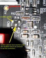
- Replacement of the 4 DAC smoothing caps with Muratas per Joe R.
- Removal or the AC coupling resistors per Ric Schultz
So far the unit sounds very revealing, but gets a little congested during complex passages. Maybe the midrange is a little thin too as in lacking harmonics. But it certainly distinguishes between the nature of different recordings.
Mods to come:
- Removing the grounding resistors at the audio out per Ric Schultz
- Upgrade the audio board diodes to Schlotky types per ganz1 & Coris
- Upgrade the audio board power supply by upgrading all the caps with in the pre DAC section per Audiocom Signature.
- Upgrade the Regulators sR3 & sR4 with adjustables per Coris
I am interested in upgrading the stock sound so I will upgrade some resistors in the signal path as Ric suggests the extant are not so good - can't hurt.
Various cap values are on order so I can't wait to try Joe's Cap across the DAC outputs after the above changes are made and burn't in.
After all the above, I will upgrade the clock section and I/V sections.
Thanks for all the help Coris.
This is probably not the recommended route for noting maximum impact but it let's see what we get.
I am intending to upgrade the decoupling Caps ce22, 44, 48 & 150 at the DAC output. The extant are Tk 220uf 25vs. I have can use 220uf25v or upgrade to 270uf35v Panasonic FCs but I am might also try similar values in the Pansonic FR which have lower ESRs and higher ripple current which would prob ably be better in this location... any thoughts?
So there is the plan save some shielding and damping of the chassis and the drive unit.
Any thoughts/Comments are welcome
cheers
PS: flame retardant liberally utilized
Welcome to the thread! Nice plan!
A real modder, I may say... I did the same many times: bought new device to the purpose of modify it....
A real modder, I may say... I did the same many times: bought new device to the purpose of modify it....
I would encourage you to remove or short the output coupling capacitors. Maybe you could tell us a little more about your setup.
Eric
Eric
Thanks Coris and eganz1...
I really enjoy doing this stuff... maybe I have a problem.. 😉
The Oppo is was bought to replace a dying heavily modded Sony scd77es ... in my audio system. I also wanted to be able to stream from a synology Nas... all works beautifully.
This feeds into a BAT vk50es then Parasound JC 1s and finally out of ProAc d38s speakers.
Interconnect s and cables are Purenote.
Appart from the Oppo, all of the other units are fully stock.
Any thoughts on the Panasonic FRs?
... . sent from an oasis in the wilderness. ... ..
Thanks Coris and eganz1...
I really enjoy doing this stuff... maybe I have a problem.. 😉
You are not the only one (heaving a problem)...😀
Last edited:
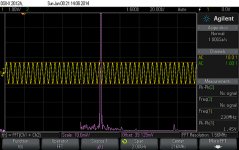
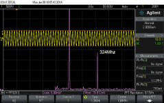
My clock divider is now up and running.
216Mhz SAW main clock, divided to 108Mhz for DAC and to 27Mhz for processor.
Here is the test bench, but finally this kit it will look better, with shorter connection pins, and soldered on the main battery board.
It need a little bit more fine tuning, but how is now it looks like in the attached scope pics.
Quite excited to "hear" the result...
Attachments
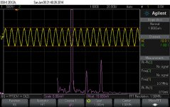
Improved 108Mhz clock signal, after some adjustments of divider circuits.
It will be for sure a second version of the divider PCB, as I found necessary with some other design improvements...
It will be for sure a second version of the divider PCB, as I found necessary with some other design improvements...
Attachments
Last edited:
Looks like it is all coming along nicely.
Have so far removed ac coupling caps and grounding output resistors... replaced smoothing caps at buffer/amplifier/mix op amps with silmic iis and post dac smoothing caps with panasonic fcs... also replaced audio board diodes with schlottky types.
Still burning in but sounds better... more integrated full sound... fuller and more precise bass... maybe a slight loss in absolute resolution especially leading edge of musical phrases... but will see after full burn in.
Next is for pre dac filtering improvement.
... . sent from an oasis in the wilderness. ... ..
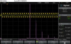
After some more tests, I have found out that the clock signals it can be improved further, at the divider chip input as at its output. So, I have decided to produce another improved version of the divider PCB.
I do hope I will get it soon, and then having the opportunity to publish better test results.
I do hope I will get it soon, and then having the opportunity to publish better test results.
Capacitor
Hello,
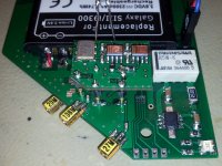
I'm beginning to tweak OPPO's 105D.
What do you think about changing capacitor SMD 220µ on the motherboard by bigger one as 470µ SEPC (OScon)
I speak about capacitor near the DC-DC converter.
Thx.
Hello,
I'm beginning to tweak OPPO's 105D.
What do you think about changing capacitor SMD 220µ on the motherboard by bigger one as 470µ SEPC (OScon)
I speak about capacitor near the DC-DC converter.
Thx.
Coris,
what is your feeling about TCXO and better OCXO ?
Do you believe that your Clock with divider should be better for a lower price ?
what is your feeling about TCXO and better OCXO ?
Do you believe that your Clock with divider should be better for a lower price ?
- Home
- Source & Line
- Digital Source
- Oppo's BDP105 - discussions, upgrading, mods...