Thanks v-bro,
I definetly think three feet is the way to go, I plan to add corner braces at the bottom to add strength and smooth the fold.
-k
I definetly think three feet is the way to go, I plan to add corner braces at the bottom to add strength and smooth the fold.
-k
Hi, how are things going?
The three feet should be as far apart from eachother as possible to enhance stability.....
The three feet should be as far apart from eachother as possible to enhance stability.....
Hello,
I woud built a TL with a PL18WO09 4ohm version + XT25TG !
I have mathcad with the worksheet. I designed a box with the offset driver in an open ended TL worksheet.
PL18 4ohm T/S
The box :
it will be a tappering TL .
L = 50inc
offset : 0.2 ( 50*0.2 = 10inch )
So=4*Sd
Sl=0.5*Sd
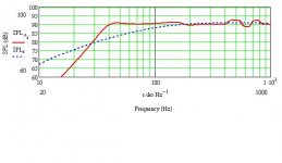
I got this SPL curve :
What do you think about it ?
Can I desing a TL with the worksheets with 2 driver ? If yes, how ?
I woud built a TL with a PL18WO09 4ohm version + XT25TG !
I have mathcad with the worksheet. I designed a box with the offset driver in an open ended TL worksheet.
PL18 4ohm T/S
The box :
it will be a tappering TL .
L = 50inc
offset : 0.2 ( 50*0.2 = 10inch )
So=4*Sd
Sl=0.5*Sd
I got this SPL curve :
What do you think about it ?
Can I desing a TL with the worksheets with 2 driver ? If yes, how ?
Attachments
VGergo said:
What do you think about it ?
Can I desing a TL with the worksheets with 2 driver ? If yes, how ?
Sim looks good. Your taper is 8:1, which might have the vent opening too small (port noise due to high velocity). Line start (So) for this driver should be no more than 3*Sd.
To model two identical driver in one box, double the Vas and Sd.
Hello,
sorry for the late respons, just I think on it how to do it !
I see this MLTQWP desing :
Here
I can desing the same in the ML TQWT worksheet if I set the
Z driver and zport from the distance of the begining of the TL line ?
Like the "zport" will be near the same far from the begining of the TL line as the lenght of line.
I attached a picture, I woud a straigth desing.
An externally hosted image should be here but it was not working when we last tested it.
I can desing the same in the ML TQWT worksheet if I set the Z driver and zport from the distance of the begining of the TL line ?
Of cource!
1(1)
Attachments
Thank you, that is very cool ! On my other computer I desing with mathcad an MLTQWT for the PL18WO09-04 and it is much better than with any other worksheets. straight and short TL line is enough, and I can use 2 driver in a normal sized box. I will post it on sunday... until I have no mathcad :-S And ofcourse thank you the table how to change the T/S parameters with 2 driver !
Gergo
Gergo
Here is the my mltqwt desing with the Vifa :
What do you think about it ?
An externally hosted image should be here but it was not working when we last tested it.
What do you think about it ?
What do you think about it ?
Your speaker drawing looks correct but the submitted FR plot says nothing apart from the supplied dimensioning i.e. the power level and excursion is left out.
I checked your design and came to the conclusion that it only would be ok and not sub-optimised if your maximum SPL requirement always stays below about 90 dB.
Hint: For better performance, double the port diameter and increase the speaker volume and length in order to lower the port air velocity.
b
1(1)
Attachments
HEllo,
Thank You for your help you are true !
I redesign itt a little with more carefull for the other curves. Enlarge the port diameter and the length of the port and a little the so sl. Do not the L of line, If it is working I woud built a smaller box. I will run this speaker with maximum 35watt RMS power.
I attached the file that I saved from mathcad, it is easier !
PL18WO
PL18WO
---> Rossz letöltési link! --->when translated--->He's bad downloads rioter! 🙂
b
:-DDD oh yes it is not working anymore.
Than :
L = 35"
Zd = 7"
Zport = 33"
So= 5"x8"
Sl= 5"x8"
rprot = 1,29"
Lport = 9"
If it is possible I woud built small but great tqwt.... If no than I will build a floorstanding one, than the L can be much longer ofcourse.
Than :
L = 35"
Zd = 7"
Zport = 33"
So= 5"x8"
Sl= 5"x8"
rprot = 1,29"
Lport = 9"
If it is possible I woud built small but great tqwt.... If no than I will build a floorstanding one, than the L can be much longer ofcourse.
- Status
- Not open for further replies.
- Home
- Loudspeakers
- Multi-Way
- opinions on vifa pl18 tl